80m – 70 cm SDReceiver
Linear Technology
Silicon Labs
WB6DHW
Microchip
Coilcraft
Downloads: All necessary software
If you have any questions about this project, please contact me at: 
Note for users still using the KTH-SDR:
After many years I switched on the KTH-SDR again and immediately encountered some problems. Below is what and how I solved it:
– The Rx would not start properly. Fortunately, this could be solved by reloading the latest firmware via the bootloader.
– After that, communication with the Si570 did not work. Loading the required USB driver no longer worked according to the manual, but could be solved by installing the libusb0 – win32 driver with Zadig. The SDR could then be calibrated again with the control software.
– I wanted to use the SDR for WSJT-X but no communication… That turned out to be due to the HamLib files. The latest version(s) no longer worked with the KTH-SDR. An issue has been reported for this at the HamLib files boys…
Features of the SDR receiver
– Module based (easy for experimenting)
– 8 HF bands (3.0-4.2 / 4.2-6.0 / 6.0-8.4 / 8.4-12 / 12-17 / 17-24 / 24-32 / 50-52 MHz or 50-72 MHz)
– Weather satellite and/or 2 m band (136-148 MHz)
– 70 cm band (430-440 MHz)
– Si570 Tunable VFO
– Build-in attenuator 0, -10, -20 and -30 dB
– LCDisplay
– USB Tuning Control by most of the SDR-software or manual by tuning knob
– Selectable tuning-step sizes, predefined amateur band frequencies
– 40 memory locations availableNote: In these documents (pdf) (Nieuwsbrief 128 and Nieuwsbrief 131) you can read the articles about this SDR receiver project, published in the Benelux QRP Club Nieuwsbrief. These articles includes photo’s and schematics, but they are written in Dutch!
How it all started…..
In the spring of 2008, Joris (KTH rf-Design), asked me to join an SDR project with him. He found a commercial chip from Linear Technology (LT5517) which is a quadrature demodulator specified for 40 – 800 MHz. The challenge was to get this chip working below 40 MHz.Joris designed a prototype PCB for the LT5517 and the LT6231 Op-amp. We intend to use the Si570 from Silicon Labs as LO, a very popular oscillator chip at this moment. This chip is very easy to control by I2C and has magnificent specifications and also a wide frequency range, depending of the type (CMOS: 180 MHz, LVDS: 270 or 1100 MHz).
One of the advantages of the LT5517 is that it needs a LO frequency of twice the receiving HF frequency. For this reason the Si570 should be a perfect solution.
First the I/Q module
We started building and testing the I/Q module, because we where very curious about the performance of the LT5517. For the VFO I first used my HF generator (PSM-5) and later the Si570 kit from WB6DHW controlled by a PIC 18F2550 which also has USB connectivity. PowerSDR was used to demodulate the I and Q signals from the board.During our first tests we experience that with sufficient LO power (> 5 dBm), the LT5517 was able to demodulate signals below 3 MHz! That was very hopeful, but how should the conversion gain react on that LO power and also on those low frequencies…..?
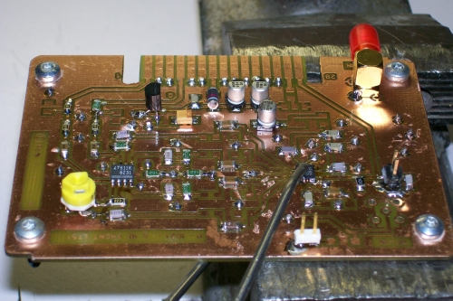
I did a test with PowerSDR and measured a steady conversion gain over the range 3 – 40 MHz. In one word magnificent!! Joris was also very enthusiastic about the results. His LT5517 was even better, he reached 1,8 MHz as lowest possible receiving frequency.Below a picture of the prototype LT5517 board. Under the special tool (a kind of spring clamp) you can see the LT5517, fit on its place for soldering. On the left the LT6231 low-noise op-amp.
The I/Q LT5517 module
The synthesizer / PIC module
Because of this success, Joris continued and design the next PCB: the synthesizer module, containing a PIC 18F2550, the Si570 and a MAV-11 amplifier.
At the same time he designed a ‘motherboard’ to mount the modules on. This was very functional because it allowed us to test the modules together.I started programming the desired software for the 18F2550. This software was written in C and compiled with the free Microchip software MPLAB and MCC18 (student version). Because it’s user friendly, I made use of the Microchip boot loader construction. You don’t need a PIC-programmer to update the firmware in the 18F2550.
The synthesizer module should be able to support an LCD module, a rotary encoder and a keypad. Also control by USB should be possible.Here you see the test bench with both, the I/Q- and Synthesizer module. On the right is the encoder and LCD.

On the left the I/Q module, next to it the Synthesizer module
Motherboard with synthesizer- and I/Q module
HF band filter module
Next step in the design was a HF module. The goal for this module was to accommodate 8 half-octave filters! From 80-meters to the 6-meter band. Because we want to built good performing filters, we need SMD coils with a Q of 50 or more. On the internet we found the Coilcraft company, a very good and friendly company with high quality coils. After testing some samples, we ordered the Coilcraft C337 designer kits which included all the coils needed for the HF-module.An imported design objective was switching the filters by pin-diodes. It took us a while to optimize the diode set-up. The switching voltage was delivered by a CBT3125 and controlled by the PCF8574 I2C I/O port.
Once the PCB was ready, we start putting the SMD parts on the board. Especially mounting the pin-diodes was a very precise job. Joris called those tiny parts ‘delouses’!I started with the first filter (3.0-4.2 MHz). After the components where in place, I connected the filter board to my PSM-5 and swept the filter. Very nice result! The theoretical values of the capacitors are even as good as in practice. This was also a merit of the Coilcraft coils.
A couple of days soldering and testing resulted in the HF module as seen below.The HF-module with pin-diode control
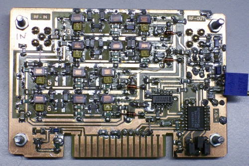
In general, the filters had a very good frequency response and with some small adjustments the attenuation of all the filters where equal within 1 or 2 dB. On the picture below you see the sweep of one filter with a ripple of about 0,1 dB.
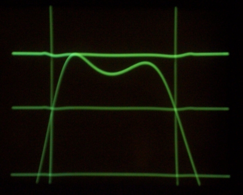
Filter response
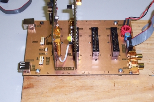
Meanwhile Joris has finished the motherboard, where the modules could placed on in connectors.
Next picture shows the board with some modules in place.
Attenuator board
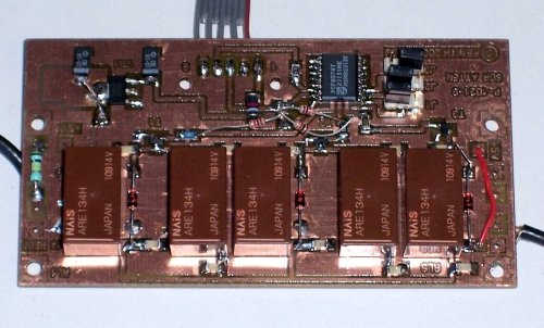
Next step was the design of the attenuator board. This board is not placed on the motherboard but is mounted to the rear panel of the aluminum enclosure (from Conrad). We have chosen for using relays in stead of pin-diodes because of the strong antenna signals in the lower HF bands. I found the (SHF-)relays on e-bay for a very reasonable price. The relays are I2C controlled with a PCF8574 8-bits I/O. Attenuation of -10, -20 and -30 dB are possible. See the picture below for details.Attenuator board
LCD and control board
Last but not leased, the LCD and pushbutton board. On this board the LCD module, also I2C controlled by a PCF8574 and 5 pushbuttons for:
– Band select (for choosing 1 of 11 pre-defined amateur bands, from 80 meters to 70 centimeters)
– Step-size (possible step-sizes are: 10Hz, 100Hz, 10KHz, 20KHz, 100KHz, 1MHz and 10 MHz)
– Tune-lock, prevents tuning with the tuning knob
– Attenuator, selection of -10, -20 and -30 dB attenuation
– Memory select and store. There are 40 memory locations available to store a frequency.The LCD board is mounted to the front panel of the enclosure.
LCD (and all other) modules
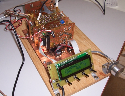
On this picture you can see all modules and boards, from rear to front:
– attenuator board
– HF module
– I/Q module
– Synthesizer / PIC module
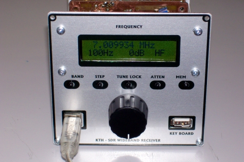
– LCD board with pushbuttons.Information on the LCD consists of:
– on line 1, the selected frequency (resolution of 1 Hz)
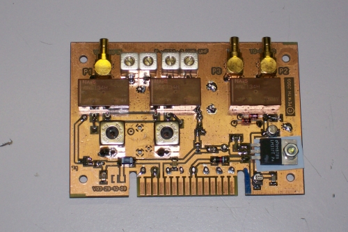
– on line 2, the step-size, attenuation and active module or memory location..VHF/UHF module
This module is equipped with a 136 MHz (Weather satellites) to 148 MHz (2 meter) band filter and a 430-440 MHz (70cm) band filter. The filters are switched by relays.VHF / UHF module
Enclosure
At the end I build all the modules and motherboard in an enclosure. We also add a foil for both panels, which gives the SDR a professional look! Below you see the result.
Front side
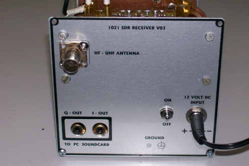
Back side
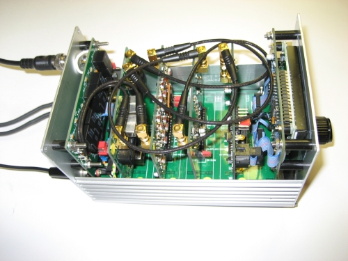
Inside
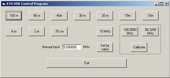
PC Control software
For controlling the module by PC or laptop, I developed a PC program in Visual Basic. With this program it’s also possible to calibrate the Si570. Below you can see a screenshot.SDR Control software
Copyright notice: The KTH-SDR project design on this page is Copyright 2010-2016 by KTH rf-Design. All rights reserved.
© Website Copyright 2010-2024 by PAØRWE