http://www.saunalahti.fi/hohtola/ham/DC-TRCVR/DCradio.htm
http://midnightdesignsolutions.com/dds60/
https://www.aa0zz.com/
http://wb6dhw.com/For_Sale.html#Si570
Modifications to the DC-TRx (August 2010)
Some disadvantages of my DC-TRx where:
– above the 14 MHz band the VFO signal was not stable and clean
– updating the firmware was not easy to do
– the use of an ‘outboard’ S-meterThe bad VFO signal was caused by the DDS-60 and the divider train (74AC86/74AC74) behind it. I decided to replace the DDS-60 by the Si570 which has already a square wave output signal available. Also the 74AC86 and 74AC74 where placed near the Si570 and no longer in dil sockets.
I had to replace the original PIC 16F628 by the 18F2550 to make USB available and for controlling (by I2C) the Si570 as well. Now updating the firmware by USB is a new feature. On the picture below you see at the top the Si570 on a WB6DHW pcb and the 74AC86/74AC74 (on their back) just below it.
VFO modification with Si570
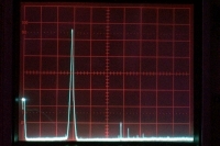
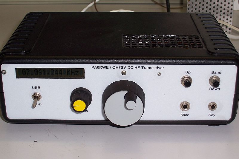
After implementation of above modifications the results where very good. Much better VFO signal above 14 MHz and also an almost perfect HF output signal. The second harmonic suppression was on all bands more than 50 dBm. Look at the (updated) pictures at the end of this page. The S-meter information is now on the display and shows (after pressing the Band button) for about 10 seconds a graphic s-meter. See picture below showing S9 signal strength.
Digital S-meter modification
How it all started in 2005….
After several experiments with DC receivers (e.g. the QRP2001), I found a very interesting DC-transceiver design of Matti, OH7SV and Juha, OH2NLT on the Internet. This design addressed me directly and I decided to reconstruct it.The Transceiver
The transceiver is based on the Tayloe detector concept. In the receiver, after the Tayloe detector, 4 op-amps amplify the LF signal, followed by a Polyphase network and a 300-2400 Hz Band Pass Filter. Below you see the block-diagram of the transceiver (with thanks to OH7SV and OH2NLT).Block schematic
In the design only ultra low noise op-amps (LT1028 and LT1113) are used to get an overall high, noise free dynamic range of 124 dB! See and read the articles on the site of OH7SV and OH2NLT.
The signal in the transmitter is going the opposite direction, from the microphone into the BPFilter and the Polyphase network to the Tayloe detector.
About the Poly phase network you can read a very nice article from Pim, PA2PIM. Take a look at Pim’s site: https://www.antennoloog.nl/polyphase-networks/
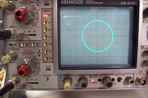
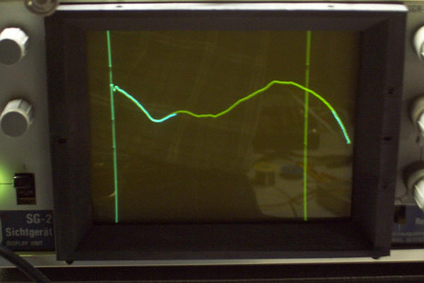
I also did some measurements to the network; I connected the two 90˚ phase outputs to the X- and Y input of my scope, and see the result:Polyphase network output
The modules
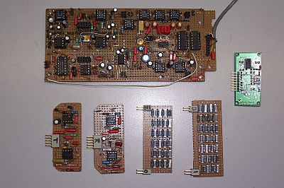
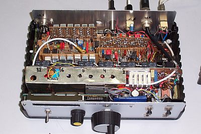
Just as OH7SV and OH2NLT did, I built a motherboard with separate modules for the Band Pass Filters and the Polyphase network. That is very practical for doing measurements on a particular module or to change it by another design. On the picture below you can see the modules below the mother print. The green module is the modified DDS60 VFO. In the other picture you can see it all build together in the enclosure. The linear amplifier (5 Watt) is described in a separate chapter.Modules and main circuit board
Insight view
VFO
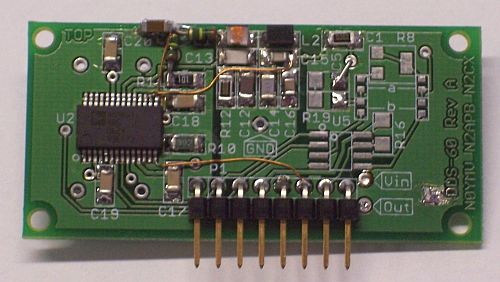
The VFO that I use in the transceiver is the DDS-60 kit, available from the American QRP Club. This VFO is built on a very small pcb (5,5 x 2,5 cm) with smd components and covers dc-60 MHz. Control is possible by PC or PIC. To get a nice square wave output directly into the 74AC86 and 74AC74 ports / flip-flop to obtain the I and Q signals for the detector, I modified the DDS60 as follows:
I first made the comparator inputs accessible on the print (they are originally grounded) before mounting the DDS
then I changed some resistors and the LPF components to get an in- and output impedance of 200 ohms
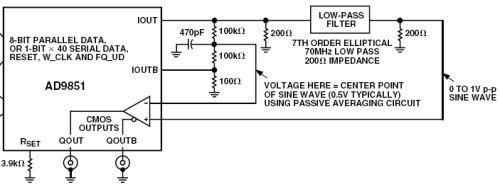
I connected both inputs of the comparator according to the data sheet of the AD9851 (see below)
DDS60 modification (schematic)
the output of the comparator is connected to the output pin of the DDS60 (the original AD8008 is not mounted).
DDS60 modification (hardware)
DDS-60 Control
For controlling the DDS-60 I use the PICELgen software designed by Craig, AAØZZ. I have added some routines to get the possibility to switch the 6 input octal filters automatically depending on the VFO frequency. Later on, when the transmitter is operative, also the output LPFilters are switched by this software. Please be aware that version 5.2 of this software has a known bug when you are using the DDS-60 for multiply by two output frequency (which is necessary for this transceiver). If you want to use the software for this purpose, I can obtain a bug-free version of the software in hex-format.Receiver Test results
I did some measurements on the receiver, such as IP3, Noise floor, Phase noise and sideband suppression. Here are the results:IP3: 11,5 dBm. It seems that the receiver blocked from about -12 dBm. I do not know the reason for it, it has to be investigated. After investigation it seems that I had made a measure mistake… Inter modulation distance (imd) is, with a attenuation of 15 dB of the input signal, -77 dB, so the new value is 77/2-15=23,5 dB!
Noise floor (3 dB): -123dBm on a band width of 2400 Hz (=156 dBc/Hz)
LO Phase noise: 120 dBc/Hz on 10 KHz, there was some uncertainty about this figure, because it could be the noise of the HF-generator itself….
Sideband suppression: When I measured it the first time, it was not better than 35 dB. I discussed that with Matti OH7SV, and he suggested to put a potmeter in stead of R1 and to use 0.1% resistors in the op-amp circuits. That was a very good suggestion: the suppression improved to 56dBm.
The 5 Watt Linear (160 to 10 meters)
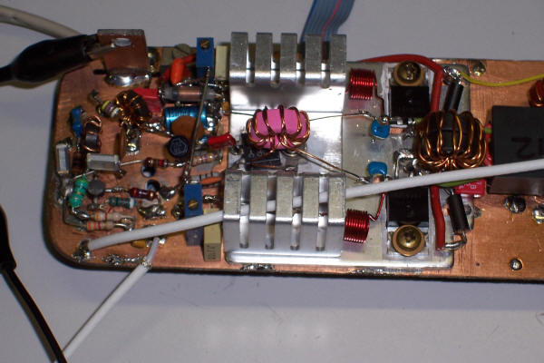
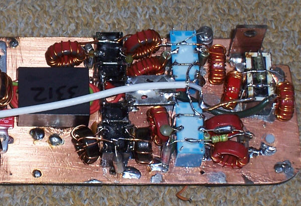
Because I want to have at least QRP-power out of the transceiver, I contact Cor, PA0CHN and he sent me his pre-amplifier design (with BFR96 and 2SC2166) of the Hartkit 45 Watt linear. The power output in my design is realized with 2 IRF510 MosFET’s and the frequency response is on all bands within 2 dB. The problem was how to find enough room in the enclosure for the amplifier. With some give and take, I finally succeeded! Below some pictures of the amplifier. As you can see on the pictures at the and of this page, the harmonic suppression on all bands meets the regulations.
Pre-amplifier with BFR96, 2SC2166 and 2 x IRF510
Output transformer and low pass filters
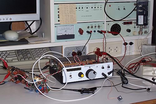
test setup
Output 1.8 to 30 MHz (markers) within 2 dB!
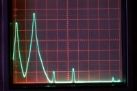
160 meters (1MHz/div)
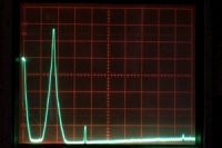
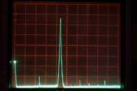
80 meters (2MHz/div)
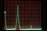
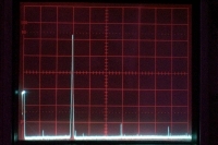
40 meters (2MHz/div)
20 meters (5MHz/div)
15 meters (5MHz/div)
10 meters (10MHz/div)