Arduino version of the AD8317 mW meter
AD8317 at Aliexpress.com
AD8317 Datasheet
![]() Downloads: AD8317_mWmeter.zip Note: This file contains 2 versions: one for a 2×24 character LCD and one for a 2×16 I2C display. I also added the Bounce2 lib.
Downloads: AD8317_mWmeter.zip Note: This file contains 2 versions: one for a 2×24 character LCD and one for a 2×16 I2C display. I also added the Bounce2 lib.
Updates
Version 1.6 Due to an error in thinking, the error correction was calculated based on the input + the set attenuation. That wasn’t right. The error correction is now calculated based on the real input signal strength.
The display also indicates with a ‘c’ when the error correction has been used.
Version 1.5 The Minus (-) sign before the attenuation value is removed.
It is now possible to reset the calibration value for one band only.
Version 1.4 The error values are included in the measured power value and removed from the display. This ensures that the value on the display more closely matches the actual measured value. The datasheet of the AD8317 was used to determine the error values.
Version 1.3 The Error values are updated according the datasheet. This error value is displayed.
The schematic of the mW meter ( 2×24 version). The 2×16 character display is controlled by I2C on pin A4 (SDA) and A5 (SCL)
After many years of using the OZ2CPU HF meter, I switched to the Arduino and the AD8317. This had two reasons: the PIC compiler was no longer efficient enough to compile the software without errors and I wanted to be able to take measurements up to 10GHz. This resulted in a new design in the Arduino Nano but using the display layout of the OZ2CPU HF meter.
In first instance I used the sketch of Joost Breed because he uses the average of a lot of measured samples in a second to display the power. That gives an accurate and stable display as well.
Secondly I added a calibration method to calculate the SLOPE and INTERCEPT by two measurements on -10 and -40 dBm. By this method you get a much accurate measurement over the complete dynamic range. For details please read the AD8317 datasheet. The calibration is done for 8 bands (HF, 4m, 70cm, 23cm, 13cm, 9cm, 6cm and 3cm) and the calculated SLOPE and INTERCEPT is stored in EEPROM.
Note: To be able to measure more accurately, it is wise to leave the input between -10 and -40 dBm. Add additional attenuators to the input of the meter if necessary.
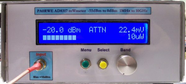
Menu functions:
– Set attenuation to 0, 10, 20, 30, 40 and 60 dB (stored in EEPROM)
– RF Power meter (default function)
– Calibration -10 and -40 dBm for each band (stored in EEPROM)
– Read calibration data for all bands
– Default Calibration data for the selected band (Reset calibration)
Calibration procedure
- Start setting the calibration value for the selected band to default (see below)
- Select the band you will calibrate
- Push the Menu button
- Select Menu item 7 (calibration)
- Set your RF generator to -10 dBm
- Push the Select button
- Set your RF generator to -40 dBm
- Push the Select button.
- Calibration completed.
- Check the calibration and if not OK do it again.
Setting Calibration value to default
- Select the band you will set to default calibration data
- Push the Menu button
- Select Menu item 9 (Zero Band Cal)
- Push the Select button.
- Default calibration of the selected band is completed.
- Start calibration
Hardware:
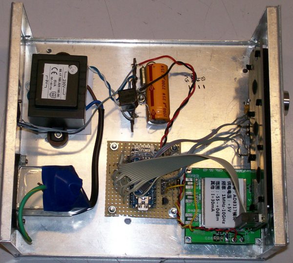
As you can see on the picture below the hardware is pure and simple.. It consists of (from left to right) the 5V power supply, the Arduino Nano, the AD8317 module and a 2×24 character module.
For the 2.048 Volt reference you can use every reference chip you like. Some parts do need a serial resistor, some do not.
Insight view