Simple GPS Stabilisied 10 MHz Oscillator by G3RUH
Downloads: PIC Hex file
I was interested in experimenting with a Jupiter GPS unit to use it later on for a 10 MHz frequency standard. First I bought a Jupiter GPS unit (TU30-D140-221) on the Internet and I found a suitable PIC (16F628) program which could be used to read the NMEA messages from the GPS unit and displayed it on a LCD. Because the source was a bit messy, I rewrote it and at the same time I understood how it all works. So I changed some information on the LCD and made it more readable.
Because there is also a RS-232 output available, it’s easy to look at a terminal program (Hyper Terminal) to the messages which are sent by the Jupiter. You can also use more dedicated programs such as: GPS Diag
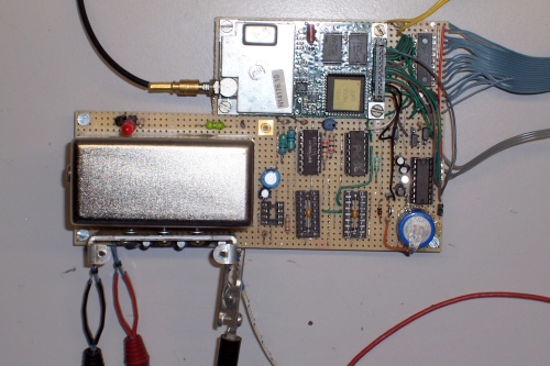
During updating the PIC program, I wait for the ordered parts and I also found on e-bay a 10 MHz OCXO, model ocxo-134-10. This is a very accurate oven controlled XO which can be tuned with a small DC voltage. I used the schematic of James Miller, G3RUH because he used the same OCXO and Jupiter GPS unit as I do. His design is using the 10 KHz signal (synchronized to UTC) from the GPS unit to phase locked it to the, divided by 10, 10 MHz signal from the OCXO.
After a couple of days soldering, the unit was ready for testing. The OCXO needed about 10 minutes for warming up. You can use the Oven Monitor pin on the OCXO to indicate that. During that time the phase-loop is trying to get the OCXO on 10 MHz but that succeeded when the oven is on temperature. The loop is then steady and vary only a bit to keep the OCXO on track.
Below you see some pictures of the project.
Testing the Jupiter GPS unit with the original PIC software
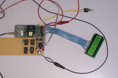
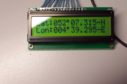
After modifying the PIC software
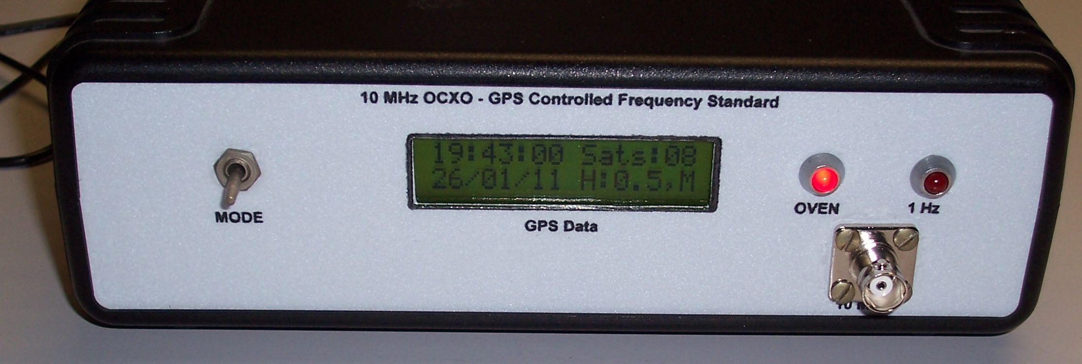
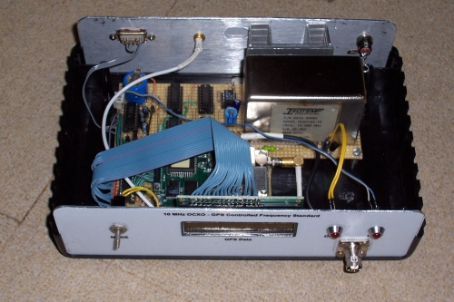
All built together
The unit built in an enclosure
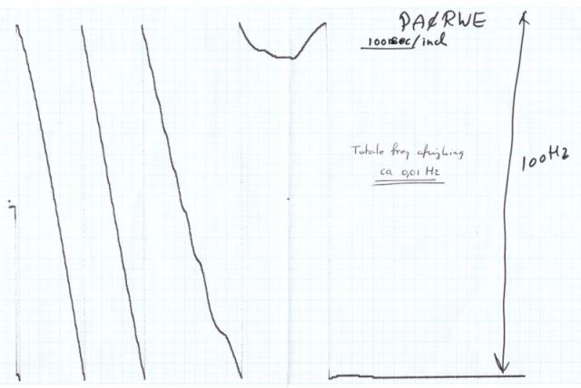
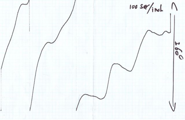
At the ‘Dag voor de Radio Amateur’ in 2011, Robert PA0RYL had setup a test environment to test frequency standards and counters. The result of testing my frequency standard was very good: the frequency deviation was between 0.00 and +0.01 Hz, after a warming up time of about 30 minutes. There was only a strange phase-jump which you can see on the phase plot below on the right.
Frequency plot
Phase plot
Wrong displayed date
If the displayed date is wrong (28-06-1997) then you have to reset the internal Jupiter date to the appropriate date.
The easiest way to do that is to use the old version 3.33 of VisualGPS.
You can find that on the VisualGPS site: http://www.visualgps.net/visualgps/Download/Download.html. Look at the end of this page where you find the Legacy version of VisualGPS (version 3.33) download.
After installation, click on Settings and then on GPS Settings. Insert this string in the string field: $PRWIINIT,A,,,,,,,,,,,,000000,ddmmyy. Check the CR and LF box. Click Add and OK. The new date will show up in the display after a couple of minutes.
Important note: Because this setting is stored in SRAM (pin 8 = high) there should be a back-up battery connected to pin 3.
Adding a CH340 USB-Serial interface
Because the modern PC has no longer a RS232 port on board, I added a USB-Serial interface. These (CH340) interfaces are very cheap available on e-bay. I had to connect the interface directly to the TTL I/O of the Jupiter GPS unit because connecting to the RS232 I/O was not working at all. To sent data to the Jupiter it was necessary to remove the MAX232 from it’s socket. Below you see a picture how the interface was mounted (glued) to the back panel (the MAX232 is still on it’s place…). I also added a screenshot of the VisualGPS program.
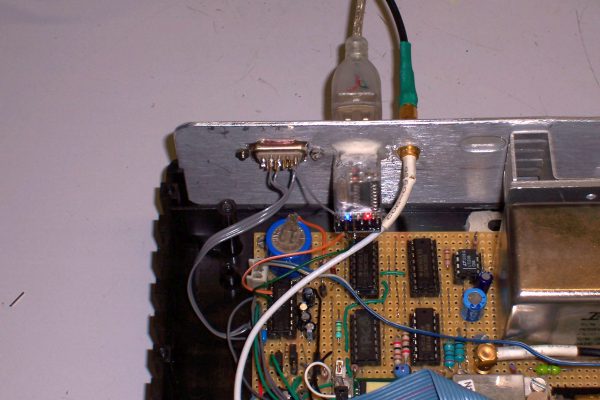
CH340 USB-Serial interface
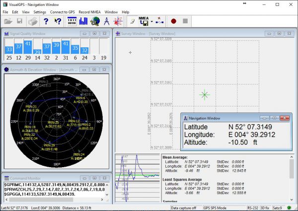
VisualGPS screenshot