http://home.datacomm.ch/hb9abx/loop1.htm
http://www.qsl.net/hb9tjx/
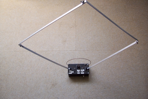
For many years I am using a Magnetic Loop antenna, designed by Klaas, PA0KSB (Silent key). This small loop works very good, also because of the built-in amplifier. It is very easy to ‘turn away’ the home-made noise. Here you can download the schematic.
Loop designed by PA0KSB, described in Electron January 1995
The enclosure has the following dimensions (l x w x h): 15 x 8 x 5 cm. Below some pictures how I construct the antenna.
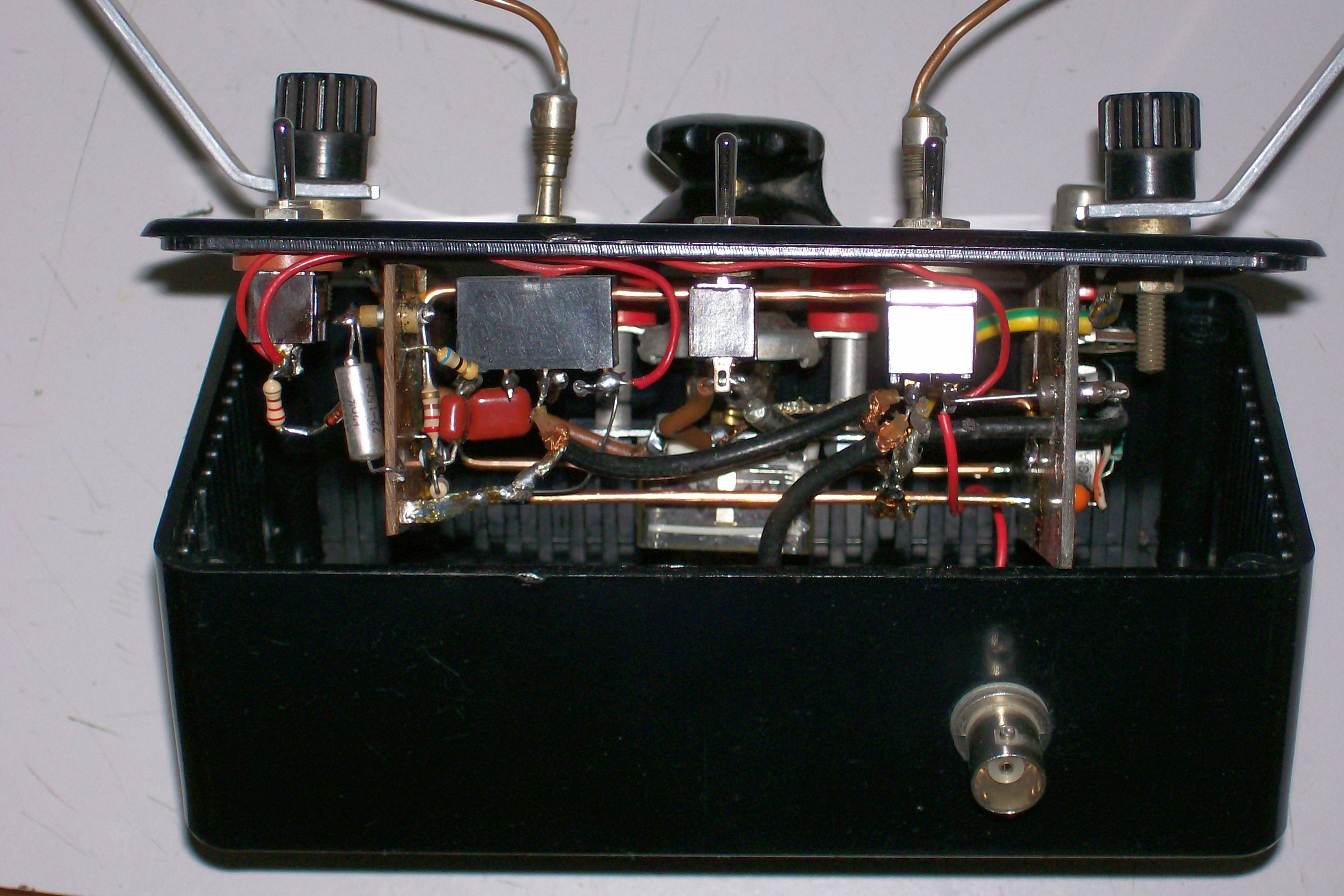
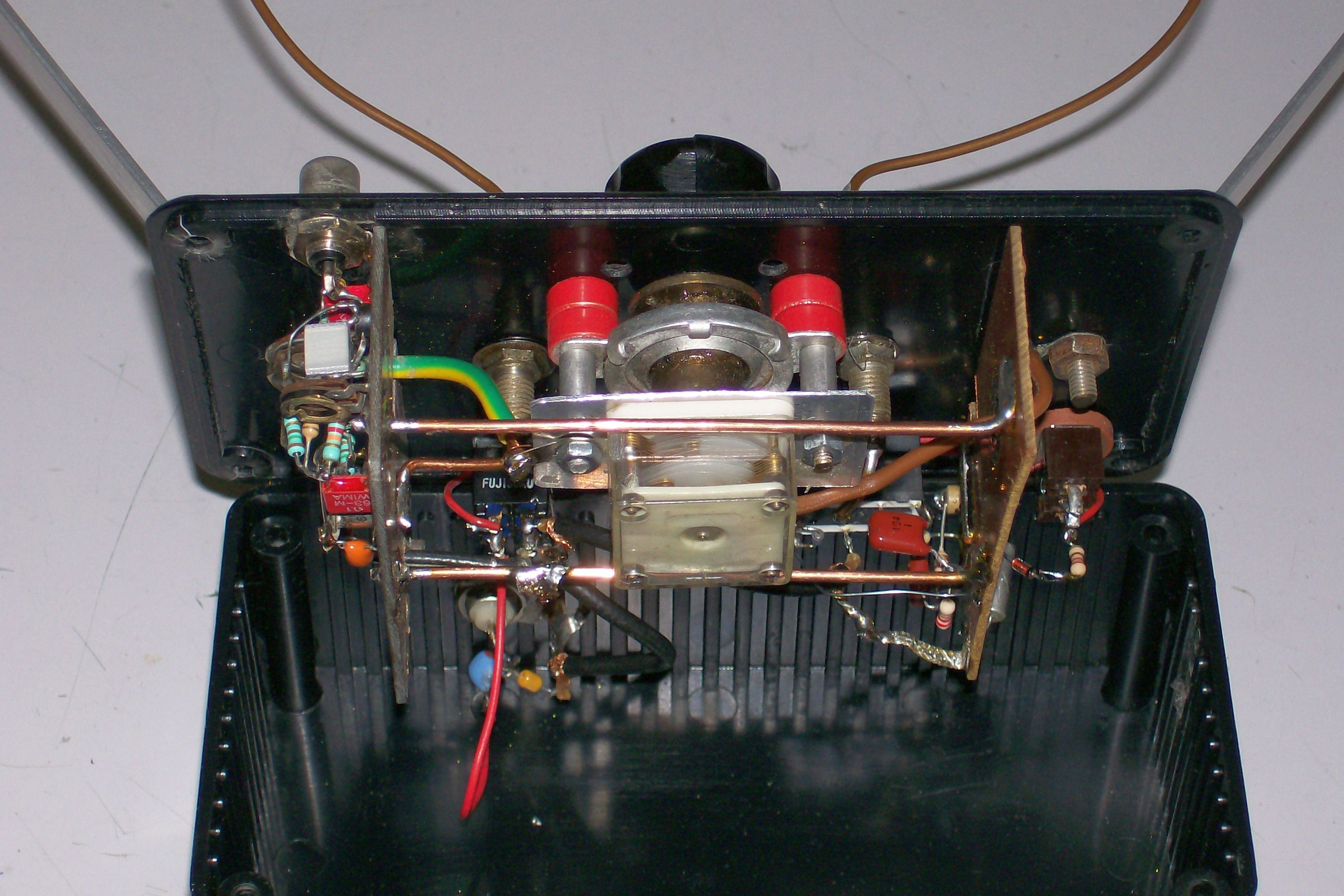
Inside view
Inside view
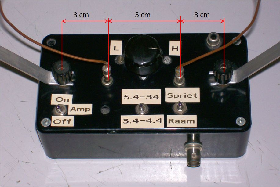
View from above with dimensions
Unfortunate, this loop was not usable for transmitting thus I had to look for an other (bigger) one.
Again on the Internet, I found many articles about Magnetic Loop Antenna’s. With some dimensions in mind, I came across the website of the East Central Indiana QRP club, where I found the loop experiments of Jeff, K9ESE. This was the design I was looking for.
Construction
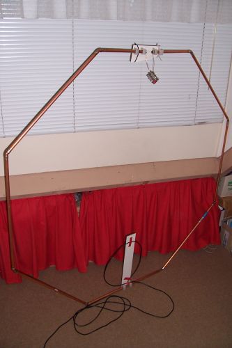
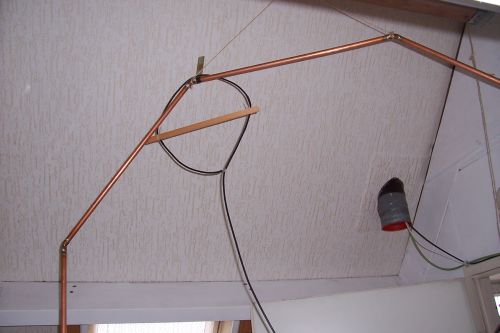
The loop is 1.6m in diameter and uses 8 pieces of 15 mm copper pipe cut to 61cm long. It tunes from 20 through 80 meters. I built it in my garage and when the loop was ready, I tried to take it up to my shack, but the loop was too wide for the staircase… I was happy that I didn’t use 22 mm tube, because I was now able to force the loop a bit to get it through the narrow stair-well!Loop antenna with faraday loop
In this picture you can see the loop, with the tuning capacitor at the top and at the bottom a so called ‘faraday loop’.
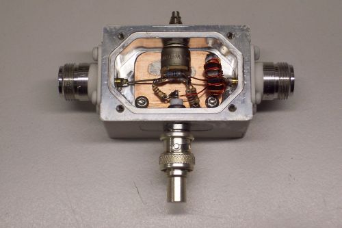
I first built a Reflection meter which, in combination with the PSM-5 measuring set, enabled me to measure the VSWR of the loop.
Reflection meter
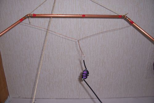
The VSWR was good on 80 meters (2.1:1). However, on 40 meters (4.4:1) and on 20 meters (5.1:1) it was not. I searched for another coupling loop design and found the site of HB9ABX, who ‘invented’ the ABXKOPPEL. This loop (with a length of half the diameter of the loop) is mounted close to the loop and both ends are brought together in the middle, slightly twisted and connected to a 1:1 current balun.
The advantage of coupling this way is the constant vswr over the entire frequency range.The ABXKOPPEL
Measurements on this coupling loop indicate a much better vswr, but the loop must still be optimized.
I also made a QSO on 80 meters with this construction and the reports were good to very good.
Tuning
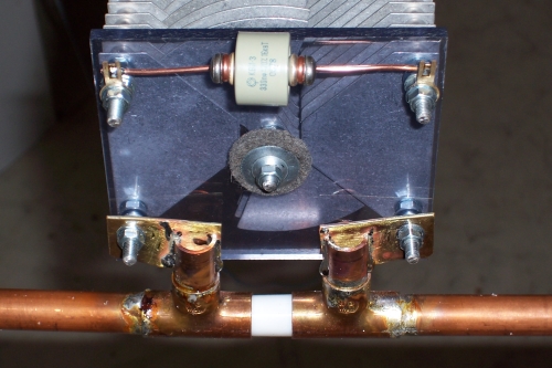
Tuning a Magnetic Loop Antenna is very difficult because of the narrow bandwidth. Therefore, in all the articles about this kind of antenna you will find a remote control tuning by means of a low rpm motor. Another very important reason for using remote control is the strong magnetic field during transmission. It is not recommended to tune the antenna with more than 5 Watt, while you are in the neighbourhood!Tuning capacitor
Another point of attention is the tuning capacitor. Because of the very high voltage, the antenna requires a high voltage capacitor. I intend to construct a so called ‘piston- or trombone-type’ variable capacitor, made from 2 copper tubes, sliding in each other. Fore the time being, I built a combination of a tuning capacitor and a band switch, connecting the right capacitors in parallel. Because of the high voltage, it cost me some capacitors….Tuning Capacitor
A friend brings to my attention HB9TJX, who made very nice varco’s and sell them as kits. I bought one and I mount a stepper motor on it to turn de varco. The stepper motor was controlled by a simple circuit with a 16F84 PIC.
Note: HB9TJX don’t sell this varco anymore.
The HB9TJX varco
How I mounted the varco to the loop
On this picture you can see how I mounted the varco to the loop. It is essential to use good metrial because of the high HF current in the loop. The parallel capacitor is to tune the loop into the 80 meter band.
Experiments with the coupling loop
Because I am always searching for the best results, I tried different coupling loops for my loop. During my measuring experiments I found that not the kind of coupling is important, but the place on the loop where the coupling is achieved! Especially on 20 meters I found a much better VSWR when I installed the coupling loop in a corner of the loop. I think that this is caused due to unbalanced electrical characteristics of the loop, maybe through the way I have connected the tuning capacitor with a switch for band selection.
I also found that my loop performs best in the 40 meter band.Here are some figures (the right 2 columns are with the coupling loop in the corner of the loop):
Loop type Frequency Return loss Signal strength Return loss Signal strength Faraday 3650 -30 dBm 144 mV -10 dBm 156 mV 7050 -12 dBm 183 mV -30 dBm 234 mV 14150 -3 dBm 75 mV -12 dBm 120 mV Variant 3650 -19 dBm 144 mV -16 dBm 156 mV 7050 -11 dBm 180 mV -13 dBm 225 mV 14150 -5 dBm 69 mV -10 dBm 126 mV As you can see, placing the coupling loop in the corner (see picture below) the Return loss on 20 meters increased from -3 to -12 dBm! Also the radiated power (measured in another small loop antenna) was higher at all frequencies.
Coupling loop in the corner…
And again…..
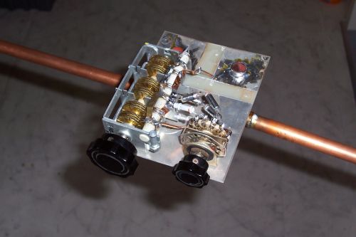
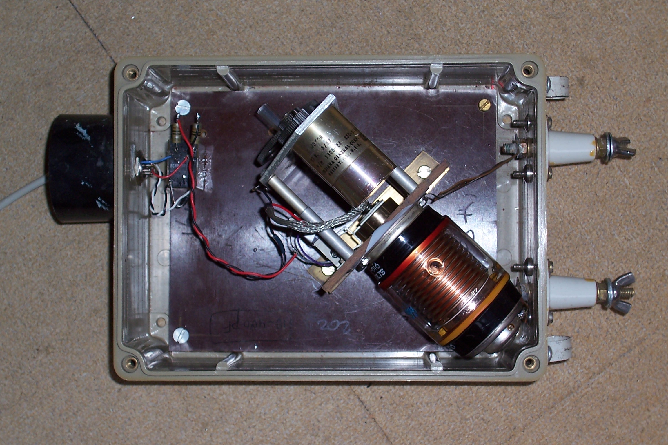
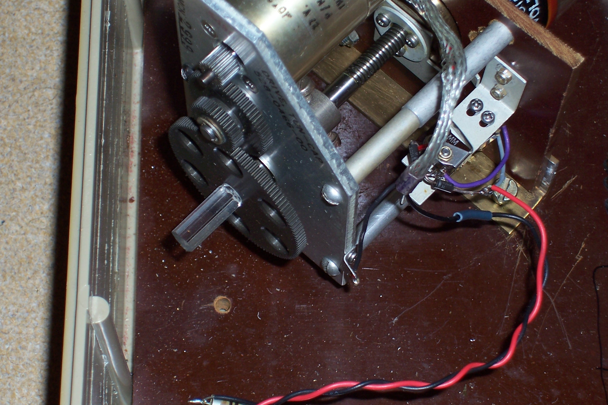
I started experimenting with the loopantenna because I bought a vacuum capacitor. I had to modify the mechanical control of the capacitor because the hardware has a negative effect on the loop quality. So I made a plastic driveshaft to isolate the motor from the capacitor.Vacuum Capacitor with motor control
Plastic shaft to isolate the capacitor from the motor
I also made a new loop from 15 mm copper tube with ‘fast’ connectors to easely assemble and disassemble the loop. Until now I did not tested this new loop….