https://www.analog.com/en/products/hmc1097.html
https://www.analog.com/en/products/adl5375.html
http://www.g4jnt.com/RxTx.htm
How it all started..
The launch of the Es’Hail satellite has given a huge boost to the DATV world, but also the SSB enthusiasts were able to add a new dimension to their hobby.
This is also the case with the Amstelland ATV collective. There, dishes were quickly installed and 13 cm power amplifiers built. But there too the idea arose to do something with SSB, and then look at an application based on I / Q technology.
Since I like a challenge, I took that monkey on my shoulder and searched the internet for I/Q SSB transmitters for the 13cm band. Nothing at all, well actually, but that was a design entirely based on standard components, but I wanted to base it on a ready-made commercial IC.
Hardware
So take a look at the Analog Devices site. There I found what I was looking for. An I/Q modulator suitable for frequencies from 400-6000 MHz. I found two types: the HMC1097 and the ADF5375. I immediately requested the necessary samples and the party could begin.
So when the IC’s arrived, I started with the HMC1097 to put it on a SMD to DIP adapter. The IC is only 4×4 mm and has 24 connections (QFN-24). So not to solder with a solder iron, but by heating the PCB at the bottom and lowering the IC in the solder with flux on the pads. After measuring, all contacts appeared to be soldered, so the first step was taken. But how are we going to modulate that thing?
The I and Q inputs are differential, so they had to be controlled in this way and there had to be a bias voltage of 0.5V. First solved this with a resistors network.
I got the I/Q LF signal from a much earlier built DC-HF set that uses the same I/Q technology. As LO I used my ADF5355 RF generator that goes up to 13GHz. Set the RF generator to 2400 MHz (the Es’Hail sat SSB input frequency) and connected to the RF input of the I/Q modulator. To my surprise, it worked. I was able to make SSB at 2400 MHz!
Since it is very important that both I and Q inputs are driven in balance and in phase to suppress the residual carrier and unwanted sideband as much as possible, this solution was not the best. Then I experimented with 600 ohm line transformers. They had a middle tap so that I could easily offer the desired bias voltage of 0.5V on both differential I and Q inputs. The result was a lot better.
I/Q with resistors network
I/Q with 600 ohm trafo
But there should be a better way. On the internet I did find an experiment by Andy G4JNT to make an AFSK modulated beacon with the ADF5375. He used the dsPIC33FJ64GP802 for this. This PIC is suitable for Digital Signal Processing (DSP). With the software of Martin, G8ASG, (see below) it was all fine for my application.
To provide the dsPIC with LF, I “picked” a circuit from my DC transceiver. This circuit uses an electret microphone and is fitted with a clipper.
This total combination was tested on a piece of printed circuit board and it worked superbly.
Added dsPIC and mike amplifier
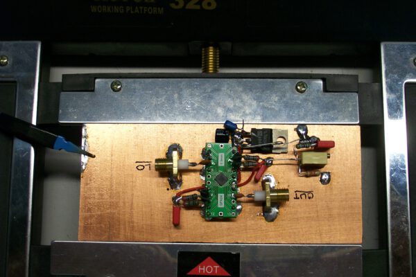
Since this concept worked, I designed a PCB for it which, in addition to the components already mentioned, was also provided with an input filter at 2400 MHz and some extra amplification at the output of the I/Q modulator to make about 15dBm output power.
My ADF5355 generator was replaced by an ADF5351 module that is connected directly (via the 2400 MHz filter) to the I/Q modulator input. I also replaced the original x-tal oscillator on the ADF board with a TCXO for better stability and accuracy.
Schematics of the I/Q board and the Arduino Nano hardware can be downloaded here.
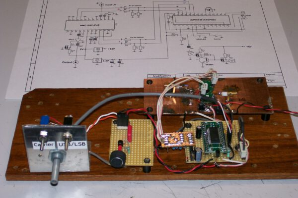
Because I was not satisfied with the LF level, I built a Speech processor. As a result, the LF level has improved considerably and thus the readability. The SP can be seen at the top of the photo to the left of the ADF4351 pcb.
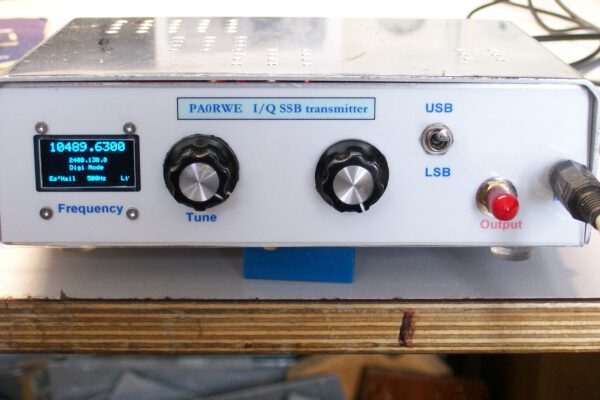
Now it was time to build all the parts in an enclosure. Below (the inside view) and on top of this page the result of the front.
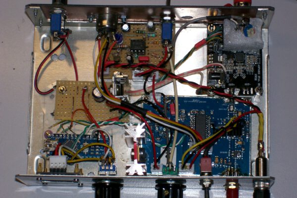
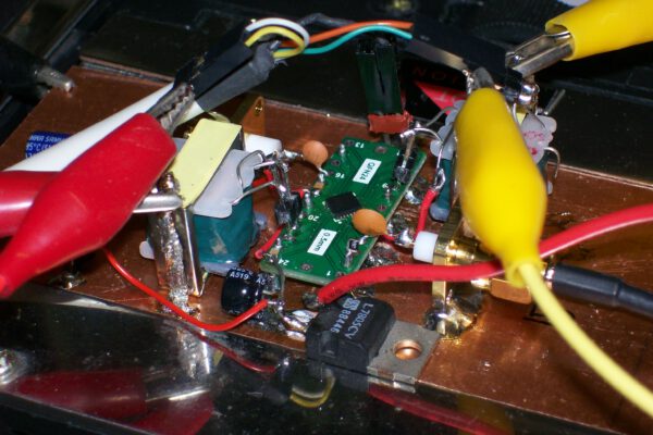
Inside view. The blue PCB is the I/Q modulator with dsPIC. Attached the ADF4351 LO board.
Software
Martin, G8ASG, had written a program for AFSK in the dsPIC in which he had also thought of a microphone input with the accompanying FIR filters. The software was also provided with LSB / USB switching and the possibility to generate a carrier.
However, I later provided the DSP software with the option to find the correct setting of the I and Q offset with two push buttons and to store this per band in the PIC. That made adjustment a lot easier. The dsPIC project software can be downloaded here.
Because the original microphone FIR filter was designed for 3400Hz I have calculated new coefficients for a 2700 Hz FIR filter and implemented that in the software.
To control the ADF4351 module, the OLED display, the encoder and the band switching in the dsPIC I used an Arduino Nano for that job. The Arduino Nano software can be downloaded here.
After all was finished, I started my first SSB transmision over the Es’Hailsat. That was great! I have got very good reports about my modulation. Below you can hear the results, received via the BATC Narrow Band WebSDR (https://eshail.batc.org.uk/nb/).
To get an idea how my modulation sounds, press the Play ![]() button.
button.