On this page you will find detail information and measurement results of the KTH-SDR
The KTH-SDR consists of the following 7 separate modules:
– Mother board
– Attenuator board
– LCD and control board
– Synthesizer module
– I/Q demodulator module
– HF module
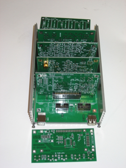
– VHF/UHF moduleMother board
This PCB consists of 4 30-pole connectors where the modules are inserted. There are receptacles on the pcb to connect by means of flat cable the Rotary encoder, Attenuator- and LCD/Control board. On the front side there is an USB-A connector for the connection to your PC and an USB-B connector for an additional keypad (not implemented option). This is not really USB but I2C! On the back side you will find an on/off switch, a DC input jack and the I/Q output lines (RCA). The DC line is filtered and un-coupled for RF. There is also a 8.6V regulator on the board to power the synthesizer module.Attenuator board
With the Attenuator board you can switch to 0, -1-, -20 and -30dB attenuation. Switching is performed by 4 relays, controlled by I2C. The 5th relay is to switch the output of the attenuator to the HF and VHF/UHF module.LCD and control board
The LCD/Control board consists of a 2×16 LCDisplay and five control buttons. The LCD display is controlled by I2C. The 5 push buttons selects Band, Stepsize, Tune Lock, Attenuator and Memory read/store.Synthesizer module
The controlling of the SDR-radio is done by the Synthesizer module. On this PCB you will find the PIC18F2550 processor and the Si570 which is the VFO for the I/Q demodulator. The Si570 is controlled by I2C and the output is amplified to get sufficient VFO signal for the I/Q demodulator. The PIC is implemented with bootloader software for easy updating the SDR firmware via the USB connection.I/Q demodulator module
The I/Q module consists of the I/Q demodulator chip LT5517. This chip has a very good linearity over a large frequency range (3-800 MHz). It is designed for a range of 40-800 MHz, but it was no problem to let it work below that 40 MHz. Stable working conditions where met from 3 MHz and higher. Therefore, unfortunately tuning to the 160 meter band was not possible. The gain of the I/Q amplifier Op-amp is adjustable or fixed as well.HF module
This module is the most complex unit of the receiver. It consists of 8 half octave filters, from 3-32 and 50-52 MHz. The filters are switched on and off by pin diodes controlled by I2C. Coils are wired, high-Q smd parts from Coilcraft. Optionally you can add an HF amplifier to it to increase the input sensitivity of the unit with about 10dB. Because the use of over 190 very small smd parts, this unit is really a great challenge to assemble!VHF/UHF module
The VHF part of this module is designed for a frequency range of 136-148 MHz. This is to get the opportunity to receive weather satellites on 137 MHz and the 2 meter band as well. The filter section is equipped with a trimmer C to tune the filter for 136-138 or 144-146 only or for the whole range of 136-146 MHz. The UHF part covers 430-440 MHz and is equipped with 2 helical filters. The filter sections are switched by relays, controlled by the PIC. To increase the gain of the module with more than 20 dB, a SGA4586 gain block is applied. There is a possibility to exclude the VHF filter and make a direct connection (with jumpers) from antenna input to the SGA4586 amplifier. This could be very useful when you use this receiver outside the filter frequency ranges or for measuring purposes.Enclosure and PCB’s
Measuring Results with a standard Onboard AC97 sound chip and PowerSDR software
Notes: – All measurements are performed on 3630 KHz except when differently indicated.
– Results can be positively influenced by using a better, professional, sound card and tune the SDR to
the dynamic capacity of this card.Frequency Response
Frequency respons
The increasing gain on 2m and 70cm is caused by the amplifier on the VHF/UHF module.
Noise floor or MDS
The noise floor is measured at 500 Hz bandwidth and according the 3dB method. It’s really hard to do because you have to measure the output of your soundcard and also need a lot of attenuation in the HF generator signal.Noise floor at 500 Hz: -120dBm (146.9 dBc/Hz)
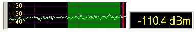
But you can also measure the noise floor using PowerSDR. The noise floor is -110,4 dBm / 111.1 dBm indicated by the PowerSDR meter at 2400 Hz. See pictures below.
Noise on 3630 KHz
Noise on 435 MHz
If you convert the 3630 KHz figure to 500 Hz: -110.4 – (+ 33.8 – 26.9) = -117.3 dBm.
IP3 and SFDR
IP3 is measured with a 2 tone RF generator on 4902 and 4912 KHz.
Without the on board HF pre-amplifier the IP3 = +27,5 dBm. When the HF pre-amplifier is switched on, the IP3 decreases to +15.1 dBm.The Spurious Free Dynamic range (SFDR) is respectively: 98.4 dB and 90.1 dB at 500 Hz.
Dynamic Range
The Dynamic Range is the distance between the MDS and the maximal signal before the soundcard gets overrun. For the KTH-SDR: -120 + 14.3 = 105.8 dBUnwanted receiving frequencies
One of the disadvantages of this detectors is receiving signals on the odd harmonic of the receiving frequency. We did measurements on this phenomenon and the results are shown in the table below.Unwanted receiving frequencies

Copyright notice: The KTH-SDR project design on this page is Copyright 2010-2024 by KTH rf-Design. All rights reserved.
© Website Copyright 2010-2024 by PAØRWE