Multiband WSPR Transmitter
http://wsprnet.org/drupal/ (You need an account for this site)
http://midnightdesignsolutions.com/dds60/index.html
WSPR Experiments and builds
After reading some interesting stories about WSPR I decided to install the WSPR software on my computer and try to receive the WSPR signals.
What is WSPR?
WSPR (pronounced “whisper”) stands for “Weak Signal Propagation Reporter”. It is a computer program used for weak-signal radio communication between amateur radio operators. The program was initially written by Joe Taylor, K1JT. The program is designed for sending and receiving low-power transmissions to test propagation paths from LF to UHF bands.
WSPR implements a protocol designed for probing potential propagation paths with low-power transmissions. Normal transmissions carry a station’s call sign, Maidenhead grid locator, and transmitter power in dBm. The program can decode signals with S/N as low as -28 dB in a 2500 Hz bandwidth. Stations with internet access can automatically upload their reception reports to a central database called WSPRnet, which includes a mapping facility.
Receiving WSPR signals
I’m using my KTH-SDR in combination with the WSPR software to receive the signals. The WSPR software is very good usable with a SDR receiver, it has special settings for it. Also USB control is working well. There are a couple of prerequisites for successful receiving WSPR signals:
– Your computer must have an exact system clock time, not more than 2 seconds variance
– Your receiver must have an accurate frequency display (not more than 10 Hz variance)
– Al signals are transmitted in USB, whatever band your are listening
– Aware of the I/Q signals of your SDR otherwise exchange them
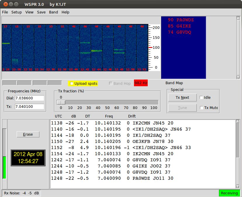
– Be patience! You have to wait until the even minute starts and then wait for 2 minutes for a complete transmission, before you know that all your settings are OK….And if it’s all OK then you will see the following screen:
WSPR screen with received stations
You see stations received in the 30 and 40 meter band. I used a simple loop antenna in my shack for receiving this WSPR stations.
Transmitting WSPR signals
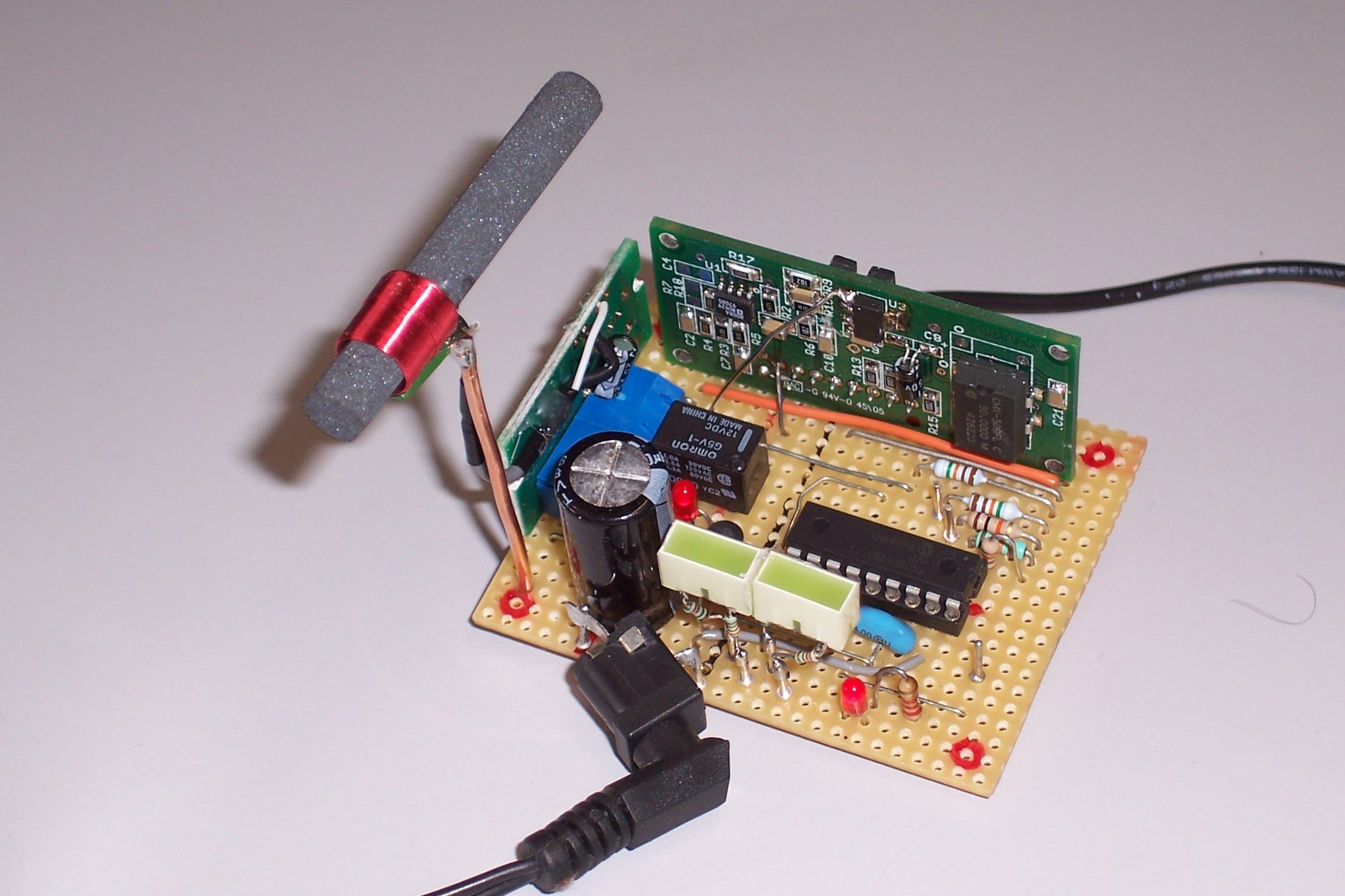
It is also very interesting to transmit WSPR signals and see the distance you have been heard. I searched the internet for WSPR transmitters and found an interesting site where you can find schematics for a stand-alone WSPR transmitter based on a PIC for control and the DDS60 (from the American QRP Club) as low-power transmitter. I build the Multi-band DDS WSPR Signal Source transmitter and added a DCF77 receiver to it to determine the exact 2-minute starting moment. This unit transmits in steps from 160 until 6 meters. Below you see the transmitter as it is running for some month.
WSPR Transmitter
On the left you see the DCF77 receiver (Conrad) and at the top of the board you see the DDS60 VFO, used as a 50 mW transmitter. The PIC used is a 16F628. I modified the software for my own purposes.
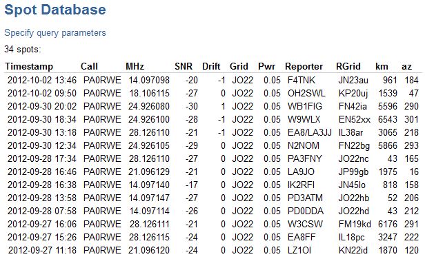
The transmitter is heard all over Europe but also in America! I’m using a 14 MHz dipole under the roof of my house.Below you see a part of the Spot Database.
WSPR spot database
WSPR Multi band transmitter with GPS clock
http://midnightdesignsolutions.com/dds60/
https://wsprnet.org/drupal/wsprnet/activityDownloads: Schematic
/ Software
Update to version 5.1: Added band selection for filtering on D9-D11. Schematic has been changed!
Major update to version 5.0:
– Possibility to transmit on a fixed frequency in 6 minutes interval, based on time slot number.
– Adding or subtracting 25Hz offset to the transmitting frequency.
– Adding the transmission band (i.e. 80m) in the display.
– Solved display crashing.Update to version 4.2: Decreased the calibration step to 100Hz for a more accurate calibration.
Update to version 4.1: Which makes it possible to use it for both the AD9850 and the AD9851.This can be selected in the software at line 128. The 80 meter frequency is changed as well in this version.
On the above mentioned site I found an Arduino sketch for making an all band WSPR transmitter. I modified the software for using a DCF clock module (Conrad #641138) and removed the QRSS part as well. But the DCF module was not a big success. It was not stable and because of the man-made noise the receiving conditions were poor in my shack.
So I decided to change it to a GPS clock. On e-bay you can find very cheap GPS modules (NEO6MV2). They are very sensitive and easy to use. After I changed the software to parts of the GPS software made by ON4CDU, the clock was running very accurate. Later on I used the Adafruit GPS library. I also modified the DDS control software because the DDS was not starting on some frequencies. I used the software from the Arduino sketch: Arduino_DDS60 made by Peter Marks http://marxy.org
The program starts by waiting for a reliable GPS signal and after the clock is synchronized it is updated every second by a timer interrupt. Within this second the program determines which frequency must be used for the next transmission on the right even minute.
Every 2 minutes the frequency is changed to the next frequency, in the same order as the hopping function in the WSJT-X receiving software. So it’s easy to automatically monitor your own signal over all the 10 WSPR bands.
The WSPR transmission is done by a mSecond timer interrupt and the complete coded message is transmitted in about 1 minute and 53 seconds. In the following 7 seconds the clock is synchronized by the GPS time and the total of received GPS satellites is displayed as well.
Important note: If you are using the software in the download, please change at line 102 – 104 the ‘XXXX’ with your own Call, Location and Output Power.
If you are not able to do that, please contact me at pa0rwe[at]veron[dot]nl .Calibration procedure
– Connect a frequency counter to the output of the DDS-60 or AD9851 module.
– Access the calibration routine by pressing and holding the ‘CAL’ push button while resetting the Nano, you will see an ‘*’ on the richt upper corner of the display
– While holding the ‘CAL’ push button press the appropriate ‘CAL+’ or ‘CAL-‘ push button to set the output frequency to 10.000000 MHz in steps of about 100Hz.
– Release the ‘CAL’ push button to store the calibration factor into EEPROM memory
– Reset the WSPR Tx.
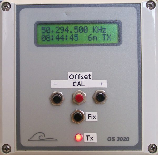
– Check the output frequencySetting WSPR on a fixed frequency
– Push the Fixed Frequency button and select the time slot frequency withe the + or – button
– When active you will see a ‘F’ at the right upper corner of the display.
– By pushing the Fixed button again, WSPR is back to normal mode.Changed the WSPR transmit frequency
– Push the CAL-libration button and change the transmit frequency in 25Hz (within the 200Hz bandwidth) steps with the + or – button.Below you see the enclosure with in the right lower corner the DDS60 transmitter producing an average 13 dBm signal. On top of the enclosure is the GPS antenna and on the inside view you see the GPS module as the small blue board. On the left, below the LCD display you see the Arduino Nano module with USB connector.
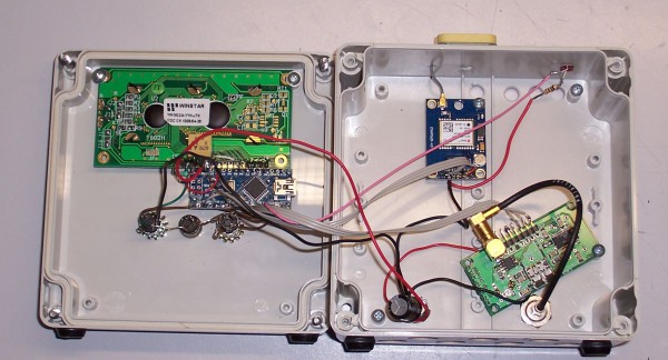
Inside view WSPR enclosure