It’s because of the NASA Apollo flights, that my interest for satellites started. After I read an article that referred to a publication of NASA in which was described how you could set up a simple weather satellite station followed by a Dutch book (“Weersatellieten” by Janssen and Schimmel) that I found concerning the same subject, I decided to set up a receiving station.
An FM receiver was built first for the 136-138 MHz band. Very soon I heard the specific 2400 Hz signals transmitted by the different satellites. That 2400 Hz signal is AM modulated with the image information and with a 4 Hz line frequency. A complete picture consists of 720 lines (180 sec).
But how do you get that slow scan image on a photograph? At that time a facsimile was popular for that goal.
My first 2400Hz Weather Satellite decoder
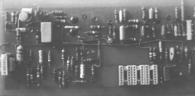
Since I did not had a facsimile the only way was to build something to display the lines on and take a photograph of it. Easy spoken, but not easy done!
First I built a decoder to get the 4 Hz sync signals and the filtered AM signal with the pixel information. After that I modified an old b/w television for what I only needed: the High voltage part, the deflection unit and the amplifier for the Z-signal. I built a new transistor based deflection amplifier with a vertical saw tooth signal of 200 seconds and a horizontal saw tooth synchronized on the 4 Hz pulses from the decoder unit.
I used a camera lens to project the pixel on photographic paper and put that in front of the modified television (in a complete dark room of course). Then I played back the recorded signal of the weather satellite and waited till the end of the picture. Then I developed the photograph and at that moment I was able to see if this construction was working! And yes, it worked, see the pictures below.
To get an idea how a NOAA weather satellite signal sounds, press the Play ![]() button.
button.
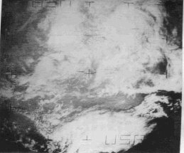
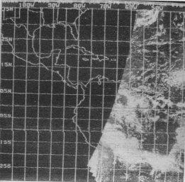
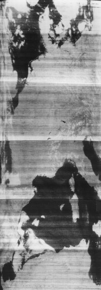
Below some pictures of the first NIMBUS- and ATS3 satellite. The ATS3 was a stationary satellite transmitting composed NOAA satellite recorded pictures.
Picture from NIMBUS satellite
ATS-3
ATS-3
The ATS3 satellite was also used for communication with scientists somewhere in the jungle. These conversations were very good to receive, in spite of this satellite being about 35,000 km far away! As antenna I used a 7 element cross Yagi that was permanently mounted at first.
On the photograph down left you see a cross dipole which registered the rise of the satellite whereupon the Yagi could be set into the right direction and than the recording was started.
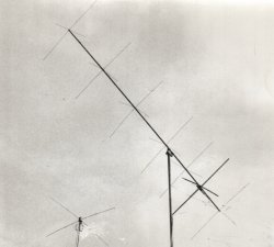
137 MHz 7 elements cross-yagi
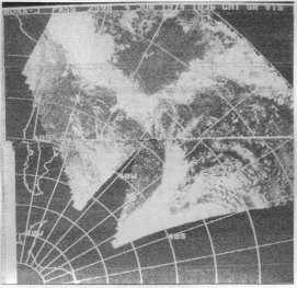
Later, this antenna was equipped with two rotors, as a result of which it could be turned in both the vertical – and the horizontal direction. So I was able to follow a satellite much longer and that resulted in beautiful pictures from Norway to North Africa.
NOAA Picture
In 1982, ‘UKW-berichte’ published an article of YU3UMV concerning digital picture processing. On a wire-wrap board I mounted and wired about 30 IC’s and the output video was connected to a b/w monitor. The result of all those electronics was a very nice picture. What was especially nice, because you could watch it at the same time the satellite was ‘in sight’.
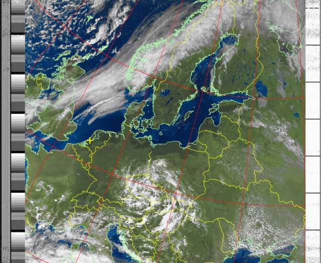
After I finished the KTH-SDR I build a stand-alone satellite SDR with parts of the KTH-SDR. Decoding of the satellite signal was done by WXtoImg software. Antenna is a 137 MHz Quadrifilar Helix Antenna (QHA). Below the results of the received picture and a picture of the QHAntenna.
NOAA18 April 2011
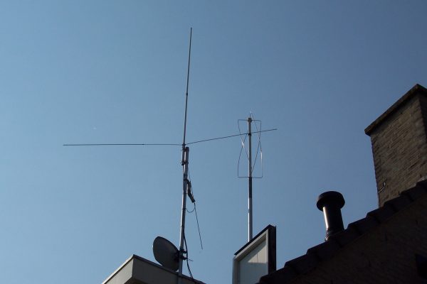
QHAntenna for 137 MHz on a separate mast