Downloads: Block diagram Front Panel Layout Schematic control part
This project started after I got a request to see whether the DDS software of PA0KSB could be adapted for a 2 meters receiver. The project should be based on the KTH-DDS kit. This appeared to be a nice project. However then not for 2 meters only, but also for 70 cm! On this page I describe and show the construction.
The Rx had to meet the following requirements:
Full use of the available KTH-DDS kit.
Reception range of 144-146 MHz and 430-440 MHz.
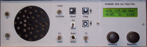
Tuning by means of up-down push buttons with steps of 12.5 KHz or 1 KHz. When using 12.5 KHz steps, the frequency must ‘be synchronized’ on factors of 12.5 KHz. I.e.: if the frequency is set to 144,4900 MHz, the next up-step should be 144.5000 MHz, or the preceding down-step should be 144.4875 MHz.
Store frequencies with the possibility to scan these frequencies.
Protection against transmitting outside the band limits.
Possibility for extension into a transceiver for both bands with possible use of repeater shift.
Construction
The receiver is built up with the following components (see pictures):
KTH-DDS kit, the 16 MHz oscillator replaced by a TCXO of 12.8 MHz and pushbuttons instead of an encoder.
LCD display with two rows of 16 characters.
2 meters and 70cm front-end with 2 x BF900 and SBL-1 (not state-of-the-art but it works).
FM IF Unit on 83,1625 MHz with a second IF on 465 KHz (the blue box). 12 KHz filter.
LF amplifier with squelch.
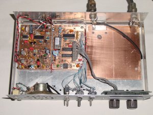
The VCO and the digital part (PIC). Some space is left for the Tx (hi)
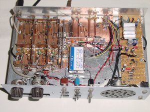
The 2m and 70cm front-ends, 5x-multiplier for 70cm, IF unit and LF on the right
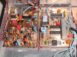
The KTH-DDS kit with TCXO
Software
The software is also designed with the possibility for transmitting. For this a trick was needed to get the VCO operating on half the transmitting frequency. The reason this frequency has been chosen is because it lies near the 61 MHz receiver VCO frequency. By halving the displayed frequency and sending it to the DDS, you get the halved receiving frequency (is halved transmitting frequency) out of the VCO. As a consequence, it was of course necessary to modify the display routine in a way that the receiving frequency (VCO + IF) and the transmitting frequency (2 x VCO) are displayed correctly! Also lock-detection was built in. As soon as the VCO gets unlocked, a warning is displayed and transmitting is inhibited.Later on, the software has been modified rather considerable: in the original design the VCO frequency was leading, but because of using the software also for transmitting (via repeaters), it was necessary to make the receiving frequency leading. This gave the following advantages:
calculation of the display frequency is simple (no IF calculation needed)
the 1 and 12.5 KHz steps change the DDS always in the same way for receiving and transmitting
calculation of IF – and divider calculations takes place before they control the DDS
a needed repeater shift can be added very simple
by means of the DDS frequency it is easy to detect if it is on 144 MHz or 432 MHz (necessary to switch to the proper front-end)
Also a new type of PIC was introduced, the 16F628. Pin compatible with the 16F84, but with much more possibilities, 2K program and 128 bytes EEPROM memory is available. However, a number of software modifications were needed to get everything working again. But now I had more I/O ports available and also the possibility of analogue measurement that was used for measuring signal strength, needed for the scanning feature.
Below a table with the different frequencies (in MHz) I used in combination with the dividers:
Receiver IF LO Divide by VCO frequency 144-146 83 61-63 n/a 61-63 430-440 83 347-357 5 69-71 Transmitter 144-146 n/a 144-146 2 72-73 430-440 n/a 430-440 5 86-88
As you can see, the required frequency range of the VCO is between 61 and 88 MHz.
Conclusion
The transceiver has the following features:
Tunable for 144.000-146.000 or 430.000-440.000 MHz in steps of 12.5 KHz or 1 KHz by means of pushbuttons.
Frequency display within 10 Hz.
Frequency synchronization on 12.5 KHz after changing from 1 KHz to 12.5 KHz step size.
28 frequency memory places. Displayed is the active memory location.
Scanning of the stored frequencies can be established by setting the start and end memory position.
Signal strength indicator on the display.
VCO unlock detection. If VCO is not locked, transmitting is impossible.
Protection against transmitting outside the bands. Reception outside the bands (within the VCO range), however, is possible.
Repeater shift for 2m (600KHz) and 70cm (+ 1600KHz) is possible.