http://www.scottyspectrumanalyzer.com/msasetcal.html
I’m starting calibrating the MSA. Read more about my experiences.
Shit happens…. during testing the PDM module (I found that the phase correction was much more than 180 degrees) I blown up the module by changing out 5V and in 10V. I’m using connectors and both connectors where the same! So now the in 10V and out 5V connectors have different sizes. But I had to build a new PDM because the PCB was damaged by the burned chips. First ordered a new PCB and then looking at e-bay for new ic’s.
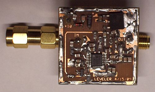
In the mean time I built an output leveler to level the output of the TG to a constant factor to do frequency calibration over the 0 – 1 GHz range. The design is from Sam Wetterlin and can be found here. It’s working very good, output stays within 1 dBm over 1 GHz range! A very helpful tool for calibrating the MSA.
Output Leveler
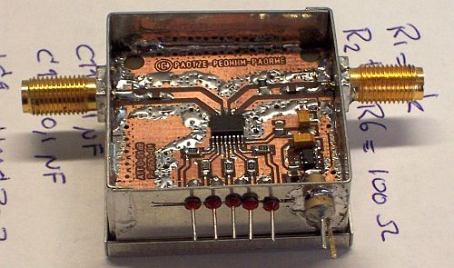
I also build a digital step attenuator with the HMC307 IC. Datasheet can be found here. The attenuation is maximal 31 dB in steps of 1, 2, 4, 8 and 16 dBm or a combination of these. I mount the attenuator behind the front panel and use it directly as input attenuator for the analyzer.
Step Attenuator
OK but now back to calibrating. I used the descriptions on the site of Scotty and followed the calibrating procedure step by step. Click here to read the calibrating procedure. I copied the text beginning at chapter II. Calibration Procedures for the MSA from the site in a Word document, formatted it and print it out. I found that easier to handle than reading it from the website because you need your computer to run the MSA software during calibrating as well.
First perform the steps described in chapter I. Initial Set-Up for MSA. Install the MSA software, set-up the hardware and set-up the software as described and perform a coarse calibration. Now you are ready for the real calibration work!
I will not describe how to calibrate, because that is what you can read on the site, but I will describe my experiences during calibrating.A. Coaxial Cavity Filter, Tuning Procedure
No remarksB. Master Oscillator Calibration
After setting DDS3 to 10 MHz you have to hit the “Continue” button and not the “Restart” button. When using the “Restart” button DDS3 is reset to 10.7 MHz and you don’t get any ‘waveform’. I’m using my GPS 10MHz standard and below the result of the beat frequency between the GPS and DDS3. Seems to be very good!Beat frequency between GPS 10MHz standard and DDS3
C. Resolving Filters in the MSA
No remarksD. Phase Detector Module Calibration
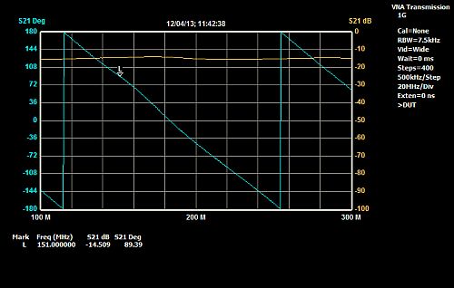
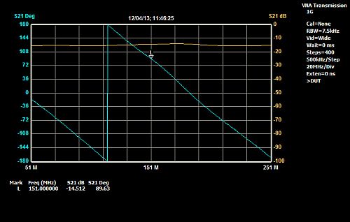
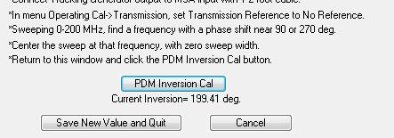
If you don’t have the VNA option, you can skip this section.I do have the VNA option so I did the calibration for this module. Set up your MSA to verify the saw tooth response. Below pictures during calibration. I found an inversion calibration value of 199.41 degrees which is high. It’s not clear what the reason is because my first PDM (before I blew up that one..) had the same high value. Even Scotty did not had an explanation for this….
Step: Select the “L” marker….
Step: The sawtooth will shift with the “L” marker….
Step: Both the Magnitude and Phace traces wiil be horizontal lines
Step: The “current inversion =” will display the newly ….
E. Path Calibration for Magnitude (and Phase for VNA)
I have used the internal Signal Generator (TG) for calibrating (needed if you have VNA implemented). First I have determined the exact output of the TG at 2 MHz with my PSM-5 measuring equipment. In my case the output is -13,9 dBm.
Then you have to follow the procedure for each RBW filter as described. Don’t forget to determine the noise floor at the end of the procedure and make the described correction on that value and ENTER it. Save the file and your MSA is calibrated!F2. Semi-Automatic Frequency Calibration for Magnitude
I did the Semi-automatic method and used the TG output Leveler designed by Sam Wetterlin. See at the beginning of this page.Frequency calibration setup with leveler
Start the MSA as described. If you are using the TG output leveler, then correct the input in the True Power (dBm) field with the correction factors as described on page 3 of Sam’s document. Remember that you have to divide these values over the frequency steps and add them to the value in the True Power value field!
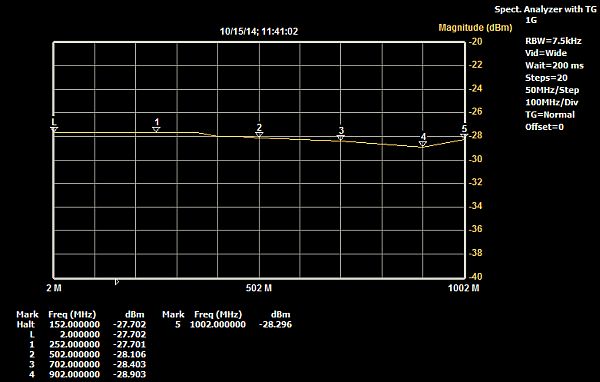
Here you can download an Excel spreadsheet which calculates the right True Power values based on the reference output @ 2MHz from TG + leveler which is filled in in cel H6. For the leveler output you can use the values from Sam’s website or measure them by yourself.Before calibration
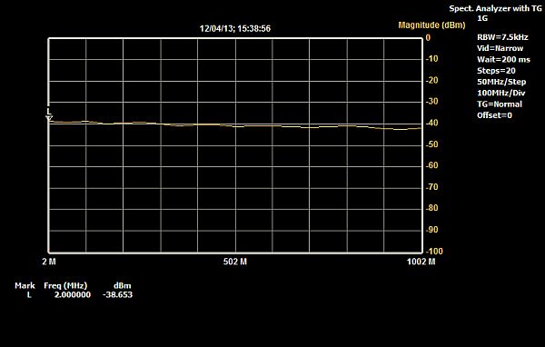
After calibration
As you can see on the ‘after calibration’ picture, the MSA shows now the leveler output including 20 dBm attenuation.
THIS PAGE IS STILL UNDER CONSTRUCTION!!