FreeSoCMini Development board
PSoC5LP information
Creator download
CWTD Explore the PSoC
Si5351 datasheet
Si5351 Adafruit breakout kit
Exploring the PSoC
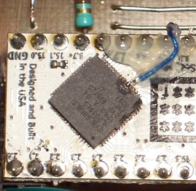
Joris (KTH rf-Design), had made my attention to an article on Internet about the PSoC and the possibility to make a stand-alone SDR with it. There was a development board available called FreeSoCMini, and we bought some of them. On the board is a PSoC5-LP (CY8C5868LTI-LP-39ES) chip, one of the latest and strongest PSoC’s.Before start developing, I read a lot of articles about the PSoC and also the already started SDR experiments . I also installed the Cypress PSoC development environment on my computer (Creator 3.0). The Cypress Creator IDE is a (great!) graphical development tool based on C and has a content of a lot of pre-defined components.
My first PSoC project
Then starting to build my first project in Creator… It was a simple project to produce a LED brightness control with a potmeter. See the CWTD webpage. I made the project, compiled it and yes it was working!Designing my own modules
Next designing a user module for my I2C PCF8574 controlled LCD based on the Cypress I2C LCD module which comes with PSoC Creator. I succeeded and the module was working fine.
But for my SDR project also I needed a Local Oscillator and my choice was on the Si570. This is an I2C controlled programmable x-tal oscillator. I designed a module for it as well, which was quite a job because there where some problems with the manual Start/Read/Write/Stop functions. When using the I2C_1_MasterSendStart() function, the I2C interrupt was enabled but the automatic I2C_LCD_MasterWriteBuf() function needed that interrupt and was not working anymore…. I added an enable I2C interrupt statement before using this automatic function. This workaround was approved by Cypress.Standalone SDR project
I started the project with functions to tune the Si570 with an encoder and display at the same time the frequency on the LCD. I also implemented different step sizes. Because I would like to have the possibility of updating the software via USB (bootloader) I made an extra USB connector on the FreeSoCMini and implemented the bootloader. It’s great to feel how easy it is to add that functionality in my project using the bootloader modules in Creator! But… it is very recommended and helpful to look at the help-video’s and searching the forums on the Cypress website if you have any problem!USB connection directly at the PSoC pins
Next the SDR part. I found the website of Simple Circuits and the SimpleSDR PSoC3 project (sorry but this website no longer exists). I imported the source in Creator and ported it to my PSoC5-LP SDR project. After making the in- and output pins available on my FreeSoCMini, I did the first test. I used my Tayloe detector based front-end (see SDR experiments) and yes, I could hear several SSB stations.
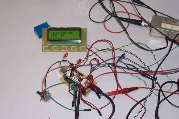
With help of Mike Hightower, the designer of the SimpleSDR, I made some additional improvements.Test set-up with FreeSoCMini
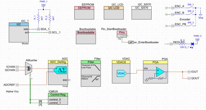
The Creator graphic design (based on the SimpleSDR design)
Receiving AM
Now SSB was working fine, the next challenge was to receive AM. I first made a simple AM detector based on the formula: sample = Square root of (I^2 + Q^2).
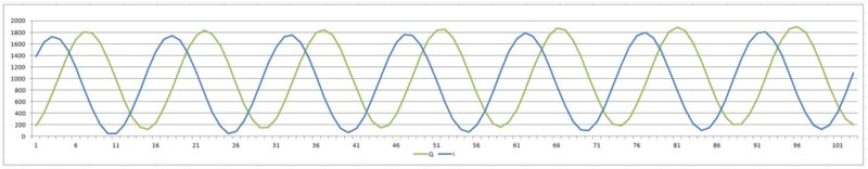
Well, that was working bad…. I hear the beat of the AM carrier stronger than the AM signal. After a lot of experimenting I found that the settings of the ADC was not good compiled. After I compiled again, the AM carrier beat tone was nearly audible.I was discussing this problem with Pieter-Tjerk de Boer (PA3FWM) and he advised me to export the data from the ADC and imported it in Excel to see where it goes wrong. But how do I export the data? Via RS232! It was very simple to add an RS232 TX module in my project and via an RS232 interface chip the samples streamed into my computer. The result where very good. Below a picture of the output of the ADC after an I/Q signal was inputted in the SDR.
I/Q output from ADC imported in Excel via RS232
The AM carrier beat tone was nearly gone but In spite of that, the quality of the AM signal was very bad. There is a lot of noise on the signal. After investigating this, I found that the problem was caused by a programming fault! I used a local variable as global and that results in an empty Q signal. After I have repaired it, AM sounds very good now!
Adding a TFT color screen with Touch Screen to the project
It seems nice to me to add a TFT screen to the SDR. I had a 2.8″ screen from the STM-32 Mini board which should be good for this job. But after days of experimenting it didn’t work… So I put this problem on the Cypress PSoC5 forum and I hope there comes a solution! Nothing was coming…
Looking at the backside of the TFT-module I found that there was a possibility to use the module in 8-bits mode using the installed latch. I changed my software for using the latch and YES!!! it’s working. Because it cost me a lot of I/O pins I decided to change from parallel mode to I2C mode. And yes this was working too, but much slower than parallel. I modified my software so that I can easily switch from parallel to I2C data control.The next step was to build a screen with touch buttons and frequency display. Cypress offers a complete graphical environment based on the SEGGER emWin Graphic Library. With this library you have a very complete set of graphical functions. Because you should have, at first use, calibrate the Touch Screen, I searched the internet and found some interesting pages about controlling and calibrating. Take a look at: http://www.embedded.com/design/system-integration/4023968/How-To-Calibrate-Touch-Screens
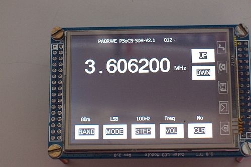
Below are the first results of using a TFT color LCD with attached Touch Screen connected to the PSoC-SDR. On the left a emWin colorbar test screen and on the right the SDR control panel.
PSoC to TFT module experiments
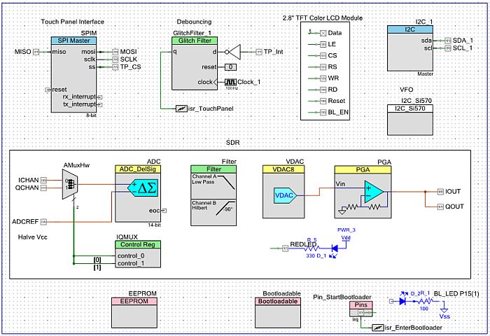
The complexity of the Creator design has been much expanded after adding the TFT module…See below.
Creator graphic design of the PSoC-SDR
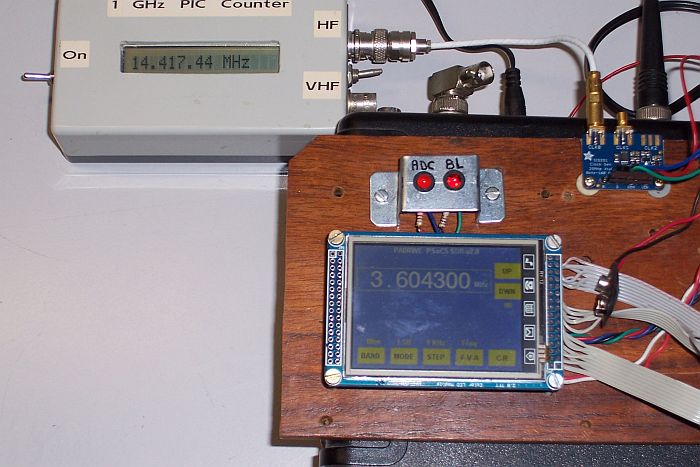
Below you see a demonstration set-up. Left the TFT touch screen module, in the middle the Si570 VFO and on the right the FreeSocMini board.
The enclosure below is the SDR front-end with I/Q output.Replacing the Si570 by the Si5351
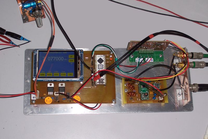
Silicon Labs has introduced a new programmable clock oscillator: the Si5351. This chip is much cheaper than the Si570 but has, depending of the type, from 3 to 8 separated output clocks. Each clock output is individual programmable with a frequency between 8 KHz and 150 MHz.Found on the internet Arduino software to control the Si5351 and I modified it for using it in the PSoC environment. That was a big job but I succeeded. Now the PSoC-SDR is running with the Si5351 VFO. On the picture below you see the Si5351 Adafruit kit on the right side.
Adafruit Si5351 kit used as VFO for the PSoC-SDR
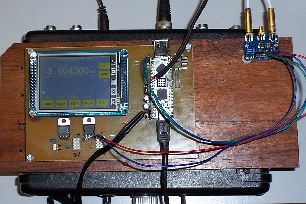
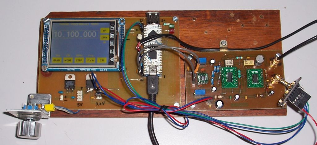
In the meanwhile, a friend of my has made a PCB for me to get rid of all the wires. See below the results of his and mine effort….
The new all-in-one PCBoard with TFT-screen and PSoC
Modification of the software to select Si570 or Si5351
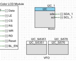
Because it’s not really simple to make a modification to the software if you have two versions of it, one for the Si570 and one for the Si5351. So I decided to combine these two VFO’s in one software version. That also meant that I had to make a Component for the Si5351 and added that to the Creator design screen. Below you see the results…2 VFO components
To make it work, I made an automatic VFO selection routine in the software based on the I2C address of the Si570 and Si5351. The complete modification was one day of hard programming, but now it’s working great. See below the screens after a reset.
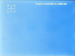
1 – Calibration
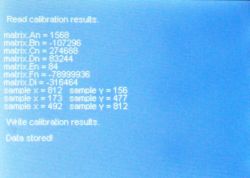
2 – Calibration results
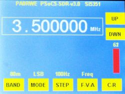
3 – SDR Control screen
Finally….
I completed building the PSoC to a real SDR. With help from Huug and Joris we started with a simple pcb for the digital part and for the RF part as well. The RF part was a pcb with separate SOIC’s for the multiplexer, the op-amp and the divider. The Si5351 was connected by SMB to the main PCB.Final pilot version of the PSoC-SDR
And some audio recordings…..:
CW on 20 meters
SSB on 3604 KHz
AM on 1008 KHz
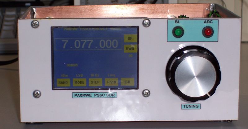
Building the SDR in a nice enclosure made from PCB material.
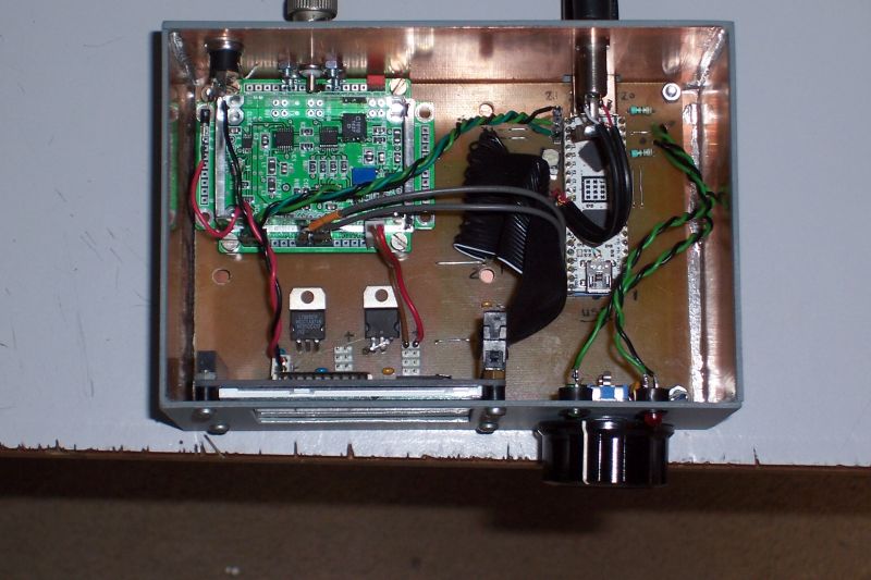
Joris decided to design a more professional PCB for the SDR front-end. Here you can download the schematic. In the Inside View picture below you can see on the left the (green) SDR front-end PCB. For more info about that PCB and availability please contact Joris at: kthkit[at]xs4all[dot]nl
Inside view with the new SDR PCB designed by Joris (see text)
Other builders
Some friends of my are busy building the PSoC-SDR as well. Below you find a picture of the complete set-up build by Tom, PA0TZE. Right from the PS0C + TFT board you find the Si570 VFO and below that, the SDR front-end. On the upper left corner of the picture, the LF amplifier.PS0C-SDR build by Tom, PA0TZE