https://rheslip.blogspot.nl/2015/01/teesy-sdr-project-update.html
https://www.antratek.nl/boards/teensy
https://learn.sparkfun.com/tutorials/teensy-arduino-shield-adapter-hookup-guide
https://www.youtube.com/channel/UCz7YtteHS_qk7aumEbhIShg (some interesting video’s how the Teensy SDR is working)
A friend of my want to build the Teensy-SDR designed by Rich Heslip VE3MKC, so he asked me to test the software and made it ready for loading it in his Teensy 3.1. Because I like that challenge I bought a Teensy and set-up my Arduino IDE for the Teensy and start testing. Besides some missing libraries the software was compiling without further errors.
But the next question was to change the original 1.8″ TFT screen to a 3.2″ TFT screen. That was some more work but I also succeeded. But the only problem is that I did not have the needed Audio shield for the Teensy to do the audio work and also display the audio spectrum including a waterfall display.
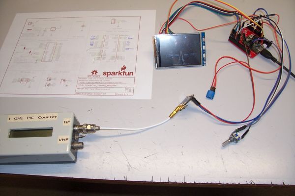
I also bought a Sparkfun Teensy-Arduino adapter to make it possible using Arduino shields on the Teensy. This board is implemented and in use for testing the Teensy-SDR software. See the picture above.
A new Teensy-SDR design…
Things are going fast… Frank, DD4WH has build his own Teensy-SDR based on the Teensy-SDR designed by Rich. He was willing to sent his software and I’m impressed how it looks.
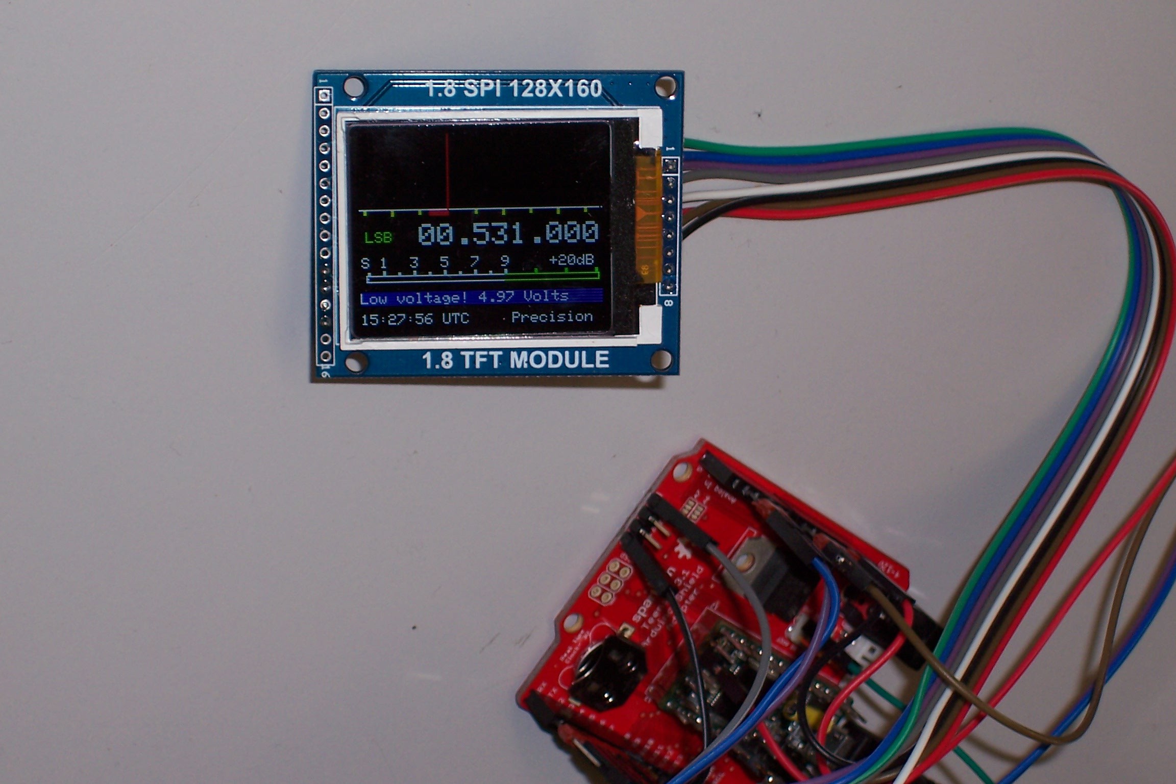
Because this SDR uses a Real Time Clock, I installed the backup battery and the clock x-tal (which is part of the Sparkfun kit) and after compiling, the RTC was running, which you can see on the display. The next step is, after I received the Audio shield, to test the SDR and replace the 1.8″ 128×160 by a 3.2″ 240×320 TFT screen ( I used the 3.2″ RPi LCD V4 screen from WaveShare).
Teensy-SDR DD4WH
I have modified the software from Frank for using a 3.2″ 320×240 pixel TFT display. That was really a job because the positions of all the displayed functions should be changed. Especially the spectrum display was a challenge! Below you can see the results. Frank has made 6 modifications on his software, which you can find (including the software) on the blog of Rich Heslip. See the link at the top of this page.
Download the Teensy-SDR software modified for the 3.2″ TFT screen (with permission of Frank DD4WH).
Latest version with better performance but not proper working sound recording download from here (New Design) or
Last but one version with good working sound recorder download from here (Old Design).
Notes:
– Both sketches are updated (10/2018) with smoother bandwidth graphics and displayed bandwidth text.
– You need the old version of the si5351 library (renamed to: RWE_si5351) the old Audio and the Time(Lib) library as well, which you can download from here . ![]()
Important notice: ![]()
– I’m using the Arduino IDE version 1.8.13. The sketch is modified for compiling with version 1.8.13. with no errors.
– But you need the Audio lib from the old version 1.40 of the TeensyduinoInstall software. This is because in the newer versions the Audio lib is updated en causes errors during compiling.
– You can find the old audio lib in the Libraries download as well. Copy that library in your libraries folder. ![]()
Building the Teensy SDR hardware
The assembly wiring diagram can be download from here.
Instructions how to assemble the Teensy-Arduino-Shield can be found here.
Using external power
If you want to run the Teensy-SDR not only on USB power, you have to remove a small track between the two pads (left from the Vin pin) on the backside of the Teensy board. See picture below.
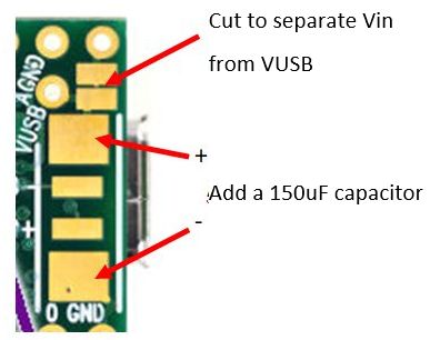
It’s also a good idea to add a 150uF capacitor on the two big pads.
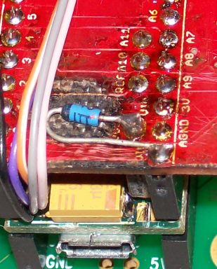
Solder on the backside of the Teensy-Arduino-Shield a diode between the Vin and VUSB connections so you can use the Teensy-SDR on USB- or 12V external power as well. Solder the cathode on the Vin point and the anode on the VUSB point. See picture below.
Before compiling make sure that the Si5351 board settings (X-tal freq and I2C address) in the RWE_si5351.h file are the right ones for your board.
Before starting the software:
– Be sure that a micro SD card (4 Gb) is inserted in the SD slot on the audio board otherwise the software won’t start.
Starting the software for first time use you have to initialize the EEPROM by the following steps:
– Remark (//) the EEPROMLOAD line in the Setup section of the sketch (Line 657 in Old Design or line 681 in New design sketch).
– Recompile the software and run the SDR.
– Save your settings with the Menu-1 Save option.
– Remove the remark (//) from the EEPROMLOAD line.
– Recompile.
– Start the SDR.
Note: When you find that the unwanted sideband (using LSB or USB) is badly suppressed then you probably are using an old Teensy Audio library. Please update in that case the library to the latest version.
Calibrating the Si5351 Clock ![]()
– Adjust the output frequency of the Si5351 with the Set Cal factor (Menu1-CaliFactor).
– Set the display frequency (for instance) at 7.000.000 Hz
– Connect a frequency counter at the test connection on the front-end board to Clock Out (=Clock2)
– Adjust the Set Cal factor so that the counter indicates 7.000.000 – 5515 = 6.994.485 Hz
– Save the setting (Menu1-Save)
Notch filter
One of the new features was the addition of a notch filter. I have to say that the notch filter is working perfect. You can change the position of the notch in steps of 10 Hz left or right to the Rx center frequency.
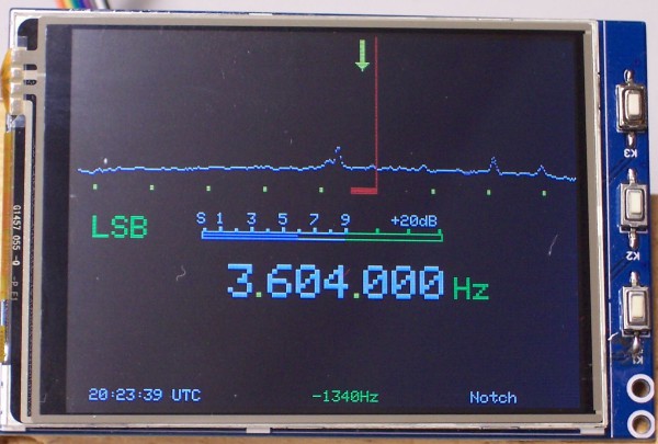
Teensy-SDR on a 240×320 3.2″ TFT (Notch is switched on)
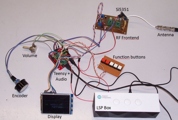
Exploded view of the Teensy-SDR
RF-Front-end ![]()
My friend Joris decided to design a more professional PCB for the SDR front-end. Here you can download the ![]() schematic. The BOM can be download here. In the Inside View picture below you can see on the right the (green) SDR front-end PCB (old version!). Front-end PCB’s are available again. Please sent me an e-mail if you are interested.
schematic. The BOM can be download here. In the Inside View picture below you can see on the right the (green) SDR front-end PCB (old version!). Front-end PCB’s are available again. Please sent me an e-mail if you are interested.
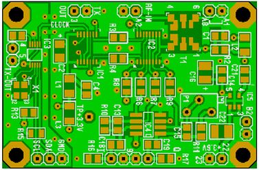
SDR Front-end
Important notes for builders:
– The text on the PCB for the I2C connections (SDA and SCL) on old boards have been exchanged! So if the CLK output of the Si5351 is not OK, please change the SDA and SCL connections.
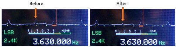
Adjusting P1 for optimal unwanted sideband suppression ![]()
– Connect your Teensy SDR to a RF generator at about 3630 MHz @ -60 dBm
– Adjust P1 as far as possible to minimize the unwanted sideband. See pictures below.
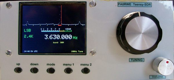
Enclosure
This week (may 2016) I have build the Teensy-SDR in an enclosure made from PCB material. Front is made from laminated photo paper. I’m satisfied by the result….
As you can see I’m now using a smaller TFT screen. It’s a 2.8″ TFT SPI 240×320 V1.1 module, bought at Ali express.com.
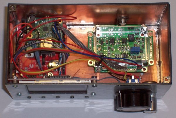
Inside view