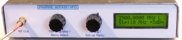
Front view
https://www.analog.com/static/imported-files/data_sheets/ADF4351.pdf
https://www.qsl.net/bg6khc/tg_new_version.htm
https://www.sv1afn.com/adf4351m.html
Downloads: ![]() Schematic PIC Hex file v3.4
Schematic PIC Hex file v3.4
Latest update (version 3.4):
Due to user comments about the accuracy of the frequency and the malfunction of the encoders, both the schematic and the software have been modified.
While changing the software I discovered that with the ADF4351 no smaller step size than 1 KHz is possible. If you wish, you will have to use the ADF4355.
Because I did not have no longer the possibility to test with an ADF4351 module, this is the latest software update.Major update (version 3.3):
I have completely rewritten the software for the VFO. I was not satisfied about the working of the encoders and the accuracy of the VFO and the calibration option as well.This is what I have done:
– Improved the working of the encoders and the push-button
– Removed the calibration option, it was not good working over the entire frequency range. I’s better using an external reference such as a OCXO or GPS frequency standard.
– Increased the maximum frequency to 4400 MHz
– Removed the 500 MHz fixed step size option (nobody is using it…)
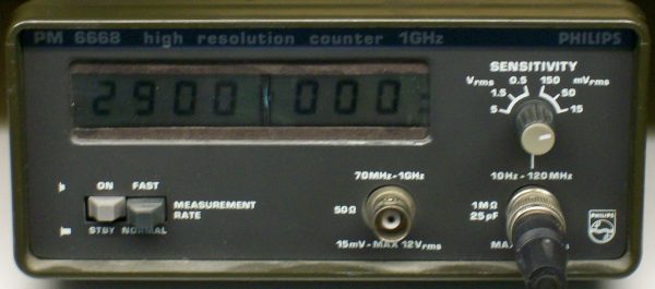
– Improved the ADF4351 register calculation (below the result of a frequency measuring with the VFO output to 2900.0000 MHz)Measured frequency with prescaler
– Added frequency store in EEPROM (Version 3.3)
Important notice: After updating the software you have to modify the hardware as well! The connections of the encoders and encoder-switch has been changed, see the schematic!
Start of the project
Friends of mine where searching the Internet for a Tracking Generator (used i.c.w. a Spectrum Analyzer). They found the website of Yanjun, BG6KHC who has built one (and also a spectrum analyzer based on the design of Scotty Sprowls, see my Spectrum Analyzer project pages). This generator was based on the Analog Devices ADF4350, a Wide band Synthesizer. The frequency range of this chip is from 137 to 4400 MHz! There is also a ADF4351 which has an even greater range: 35 to 4400 MHz. Both chips are pin compatible.So I decided to use the ADF4351 chip to design a VFO and see how it works. Before I could start I asked Yanjun if he was selling his PCB’s and he did. After a week or two, the boards arrived and I start building the VFO and the PIC (18F452) control PCB to control the ADF4351.
In addition to that: SV1AFN is also selling a nice ADF4351 board.Because the PIC board of Yanjun was in a experimental stadium, I had to made some modifications to it, e.g. the PIC working now on 3.3V in stead of 5V because the ADF4351 is running at 3.3Volt as well. For that reason I added a 3.3V regulator on the board. Also Yanjun has added the 3.3V regulator on his newly designed board.
I also modified the software to get a VFO with a lot of extra (menu controlled) features.Selecting the menu by pressing the menu button on one of the encoders (you will see *M in the display) with the following functions:
– Select internal (25 MHz (new!) or 30MHz) or external (10 MHz) reference frequency. When selecting external 10 MHz reference, the 25 or 30 MHz oscillator is disabled (depending if
the ADF4351 board has an x-tal oscillator with Tri-state control)
– Changing frequency in different step sizes: 100 MHz (separated encoder) and 10, 1 MHz, 100, 10, 1 KHz and 100Hz
– Changing power output in 3dB steps from -4 to +5 dBm
– Low noise or low spur output (experimental state)
– Fixed frequency option (starting at 500 MHz and a fixed step size of 500 MHz)
After pressing the menu button again you will be returned to the last used frequency and settings.A special note about the used encoders: There are different types of (cheap) encoders. The C (ground) connection is sometimes in the middle or at the left side of the 3 connections, looking at the top of the connections. When you connect the encoder wrong, it’s not working (well). See the note on the schematic.
Earlier Modifications
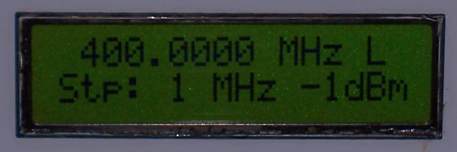
Display lay-out (February 2017)
Because I missed the information about the actual output power of the VFO (set with the Menu function), I added the selected output power on the second line of the display. Software version is: Version 2.2.
Added a 25 MHz reference oscillator selection to the menu (June 2017)
On e-bay you can buy cheap ADF4351 modules but they are using 25 MHz as reference. For that reason I added a selection option for 25 MHz reference in the menu. I also repaired some small display bugs… Software version is: Version 2.3Below some pictures of the VFO.
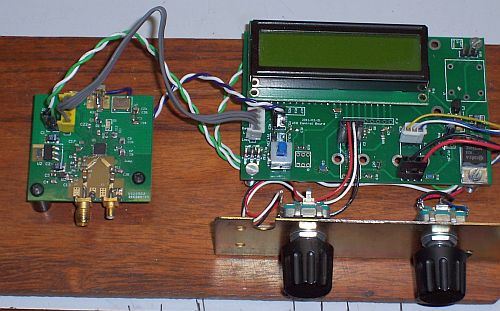
VFO in test
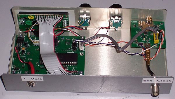
VFO insight view