https://www.silabs.com/Support%20Documents/TechnicalDocs/Si5351-B.pdf
https://www.microchip.com/wwwproducts/Devices.aspx?product=PIC16F1825
https://ak2b.blogspot.nl/2015/04/multi-featured-vfo.html
PIC version
Downloads: Hex file for the 16F1825 click for 25MHz version or 27MHz version. For control board schematic click here and for the Si5351 board click here .
Update v.3.0 october 2023: Due to the 25 MHz version not working properly, it has been updated. The 27 MHz version has also been adjusted accordingly (not yet available).
**** Please scroll down for the Arduino version! ****
This VFO is based on the popular Si5351. It consists of two parts: the controller board and the Si5351 board. Both designed by Joris (KTH rf-Design).
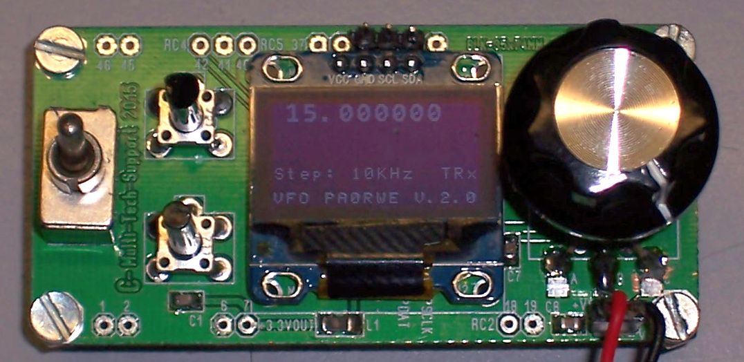
The control board is using a PIC16F1825 and the popular OLED SSD1306 display.
Because there are two versions of the Si5351 with different I2C addresses and different x-tal frequencies, I made two versions of the software, for 25MHz and 27 MHz x-tal frequency.
The Adafruit board is using a 25 MHz x-tal and I2C address = 0xc0. The KTH-Si5351 board is using the Mouser Si5351 and a 27 MHz x-tal and I2C address = 0xde,
There are 3 clock outputs available having the following outputs:
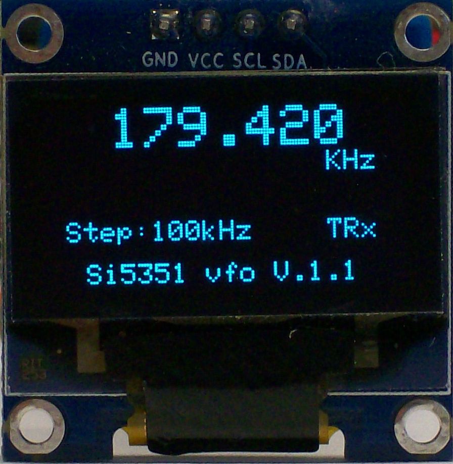
CLK0: Tx Output frequency from 1 – 125 MHz (same frequency as on the display).
CLK1: First Rx LO calculated from CLK0 + or – CLK2.
CLK2: Rx IF frequency. For instance 9 or 10.7 MHz. Every frequency is possible.
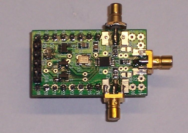
Si5351 board
The two push buttons are for Calibration and selecting (and tune) the IF frequency.
The toggle switch is for selecting RIT. With this function you can tune the Rx frequency separate from the Tx frequency.
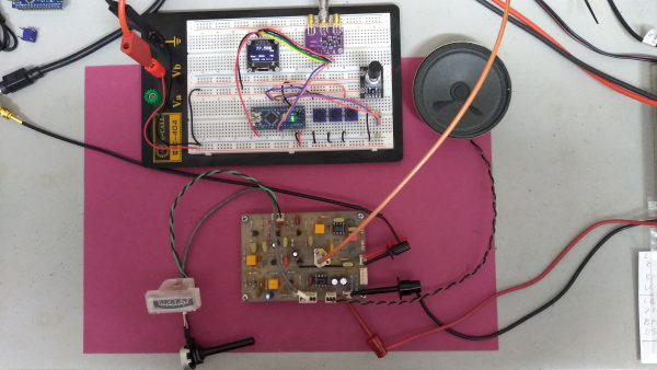
Below you see a test setup.

Si5351 VFO test setup (PIC version)
Functions:
– Output of 3 different frequencies (Tx, Rx, BFO/LO) on CLK0-CLK2
– Select and tune BFO/LO to any IF frequency
– Rx frequency based on Tx +/- BFO/LO
– Calibration function (see below)
– RIT function (only the Rx frequency is tuned with 100 Hz step size)
Calibration:
– Push the calibration button
– The frequency will be set to the X-tal frequency
– Measure the frequency at CLK0
– Tune to the measured frequency and push again the calibration button
– Calibration is ready.
Note: If calibration will not succeed: You can reset the calibration by pressing the Calibration button twice without tuning. Then try again to calibrate.
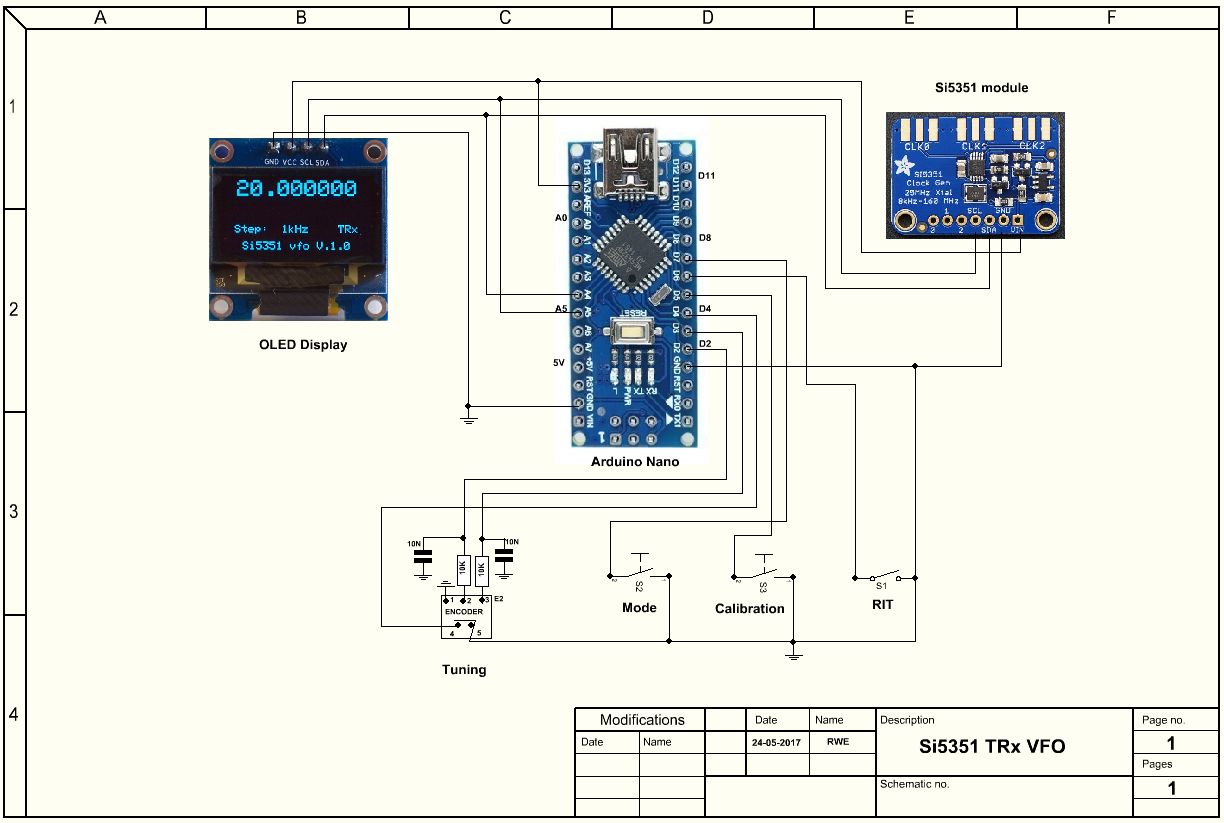
Arduino version
Due to the popularity of the Arduino, I rewrite the PIC software for using an Arduino-Nano.
The software has the same functionality as the PIC version. The Arduino version is partly based on the original MultiFeaturedVFO software of Jason Mildrum, NT7S and Przemek Sadowski, SQ9NJE.
You find the settings (x-tal frequency and I2C address) for the used Si5351 board in the RWE_si5351.h file.
Notes:
- Note about the OLED display resolution: From builders I understand that the default resolution in the Adafruit SSD1306 library is set to an incorrect value. You must change the resolution in the Adafruit_SSD1306.h file to 128×64. It is a #define statement at the beginning of the file.
Modifications
I have modified the sketch so the lowest frequency is now 10 KHz. I modified the display routine as well because it crashed when the frequency was below 100 KHz ;-).
The maximum tunable frequency is set to 100 MHz.
Update to Version 2.0 (June 2020)
Due to comments from builders, I made the following improvements to the sketch:
– Changed text BFO to IF
– Make it possible to use the vfo for upper or lower mixing by using a #define statement (upper or lower)
– Store of actual frequency after 5 seconds of not tuning
– Set Hz digit of frequency at start to zero (0)
– Step size was not saved. Repaired
Update to Version 3.0 (april 2021)
– I added the option of stepping back to the step size in the software. By holding down the step size push button a little longer you can step backwards.
Update to Version 3.2 (april 2023)
– I fixed a persistent error. A variable was filled incorrectly, causing strange errors.
Note: Because the newest version of Jason’s Si5351 is not compatible with my sketch, I’m using the 2015 version of the Si5351 library and renamed the source files to RWE_si5351).
I also make some changes for using the Arduino on FreeBSD compiler (Thanks to Joerg, DL8DTL).
For that reason you can download this updated library from here. (This zip file also includes the Rotary library).
For downloading the latest Arduino sketch version 3.2 click here. For the schematic click here.
Special version for the PA3EPQ Taurus 20
On request of Ben, PA3EPQ I made a special version for the Taurus 20. Click here for downloading this version. ![]()
For more info see the BQC Nieuwsbrief #185 and #186.
 Tx on CLK0 | 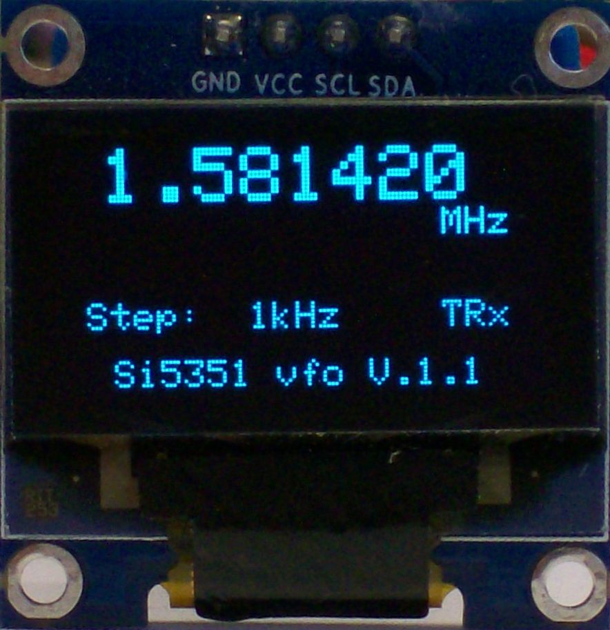 Tx on CLK0 | 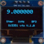 IF / BFO on CLK2 | 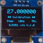 Calibration X-tal frequency |
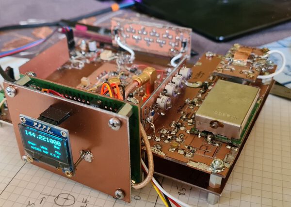
VHF Version of the vfo. 
I was asked by several amateurs about a VHF version of the VFO. I have adapted the software for this so that it can reach a maximum of 150 MHz. However, this frequency is only available on CLK0 due to the internal organization of the Si5351. The capabilities of this VFO are similar to those of the VFO described above, except that only CLK0 is activated.
For downloading the latest Arduino sketch of this VHF VFO version 3.0 (September 2022) click here ![]() . For the schematic click here.
. For the schematic click here.
Notes:
- This version of the Si5351 VFO is using the Si5351 library of Ethertkit version 2.1.3!
VFO build by other amateurs
A lot of amateurs already build the VFO. Norbert, DG1KPN has build a VLF receiver using this VFO.
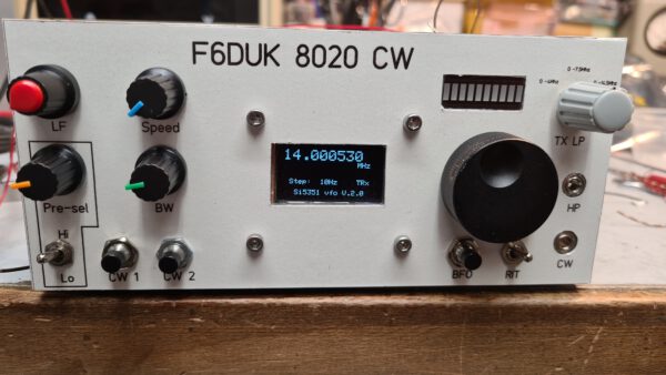
This is my VFO used in the 8020 CW tranceiver build by Hubert, F6DUK.
Hubert, F6DUK also uses my VHF VFO for his 144 MHz project….