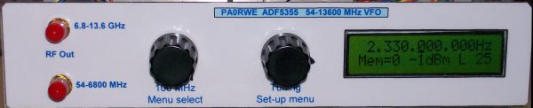
Front view
https://www.analog.com/media/en/technical-documentation/data-sheets/ADF5355.pdf
https://f6kbf.free.fr/html/ADF5355%20and%20Arduino_Fr_Gb.xhtml
https://github.com/F1CJN/ADF5355-ARDUINO-LCDShield
Downloads: Schematic and Sketch-v1.6 Sketch-v1.7
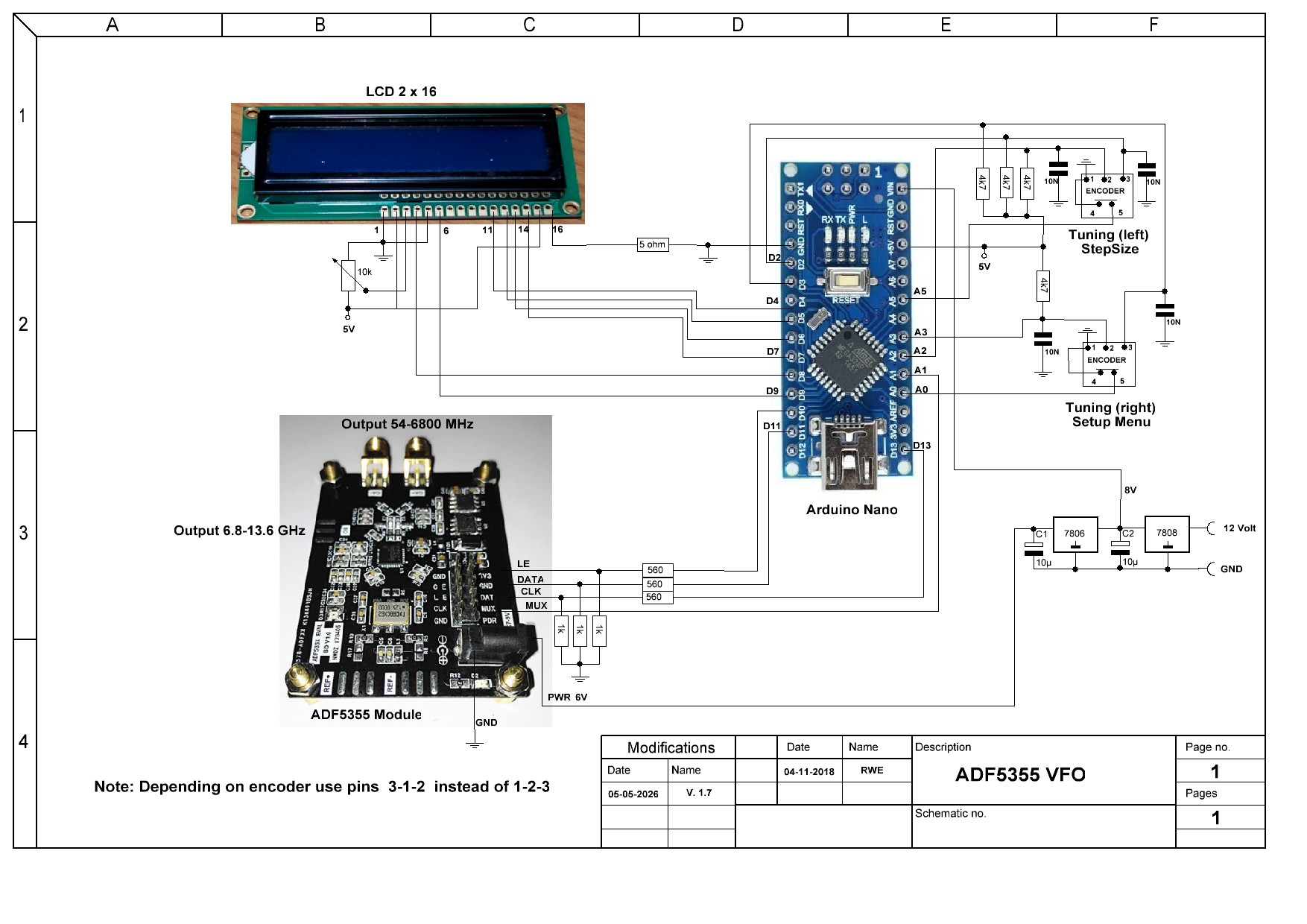
Note: The sketch and schematic is updated (May, 2026) to version 1.7.
– Added is the possibility to set the step size with the push button of the left encoder (if present)
Because I had to use the ADF4351 board for my new BATC Portsdown DATV project, I decided to rebuild the ADF4351 VFO with a ADF5355 module, bought from e-bay. I also replaced the PIC by an Arduino Nano. The software (sketch) is based on the design of F6KBF and F1CJN. I have replaced the push buttons in the design by two encoders and I have added menu functions.
The frequency range is automatically split over two output SMA connectors: 54-6800 MHz and 6800-13600 MHz
The VFO is menu driven and has the following functions:
– Selection of one of ten memory locations
– Step size selection ( 1, 10, 100Hz, 1, 10 100 KHz and 1, 10, 100, 1000 MHz) by means of the Menu or the 100MHz encoder push button (version 1.7).
– Output power settings: -4, -1, +2, +5 dBm (strongly depended on selected frequency) and not working on the >6.8 GHz frequenties output
– Reference input frequency: 10, 25, 100 and 125 MHz.
You can reach the menu functions by pressing the Right encoder.
The last used frequency is automatic saved after 5 seconds of not tuning.
In normal use the Left encoder is for standard 100 MHz steps.
The Right encoder steps according to what you have set, i.e. what the cursor is underneath.
If you press the Right encoder button you will enter the menu.
With the Left encoder you set the menu item, i.e. Memory, Stepsize, Output and Ref frequency.
With the Left encoder push button you can set the stepsize as well (version 1.7)
Once you have selected a menu item, use the Right encoder to select the desired setting for that item.
To select a stored frequency:
Press the Right encoder button (you will immediately enter the Memory option)
Select the stored frequency (0 to 9) with the Right encoder
Press the Right encoder button briefly. The saved frequency is now active.
To store a set frequency:
Set the frequency you want to save.
Press the Right encoder button (you will immediately enter the Memory option)
Select with the Right encoder where the freq should be stored (0 to 9)
Press the Right encoder button for 3 seconds. The frequency is now stored.
Builders information
The price of the board is much more expensive then before the corona pandemic. It increases from $66 to over $100 (on eBay)!!
Using the ADF5355 module it’s very easy to build the VFO.
Because the ADF5355 is using 3.3Volt I/O you have to pull-down the output of the Arduino Nano 5Volt I/O by voltage dividers (see the schematic).
Programming can be done with the Arduino IDE and the Arduino Nano USB bus.
I have replaced the original X-tal oscillator by a TCXO for a better frequency stability. See: https://www.digikey.nl/product-detail/en/connor-winfield/DV75C-025.0M/CW885CT-ND/5641655
Using an external ref. frequency you have (by using REF+) to remove R10 and put it on location R17. For using REF- remove R5 and put it on location R8. (They are 0 ohm and according my board).
It’s also a good idea to block the not used RF OUT connection with a 50 ohm SMD resistor.
Caution: The total supply current is (depending on the RF divider and output power) between 160 and 250 mA. For that reason I added an aluminum cool block on the ADF5355 and I added a separate 6V regulator as well (mounted in the middle of the back panel of the enclosure).
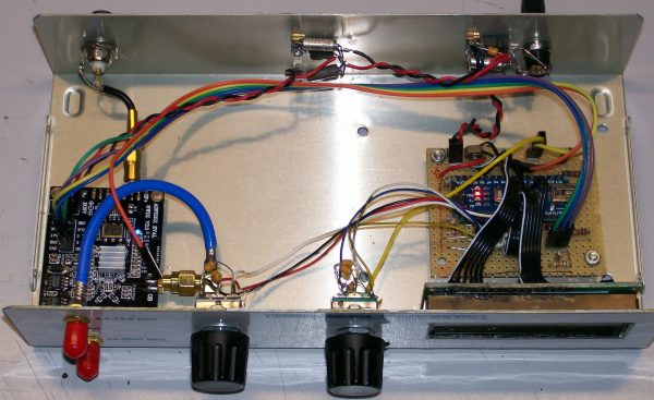
Insight view